Method and a jitter buffer regulating circuit for regulating a jitter buffer

a jitter buffer and regulating circuit technology, applied in the direction of multiplex communication, time-division multiplex, electrical apparatus, etc., can solve the problems of limiting the flexibility of jitter buffer regulation, regulating the desired delay, and further delay in data transmission, so as to achieve low data packet losses

Inactive Publication Date: 2004-09-23
UNIFY GMBH & CO KG
View PDF5 Cites 12 Cited by
  • Summary
  • Abstract
  • Description
  • Claims
  • Application Information

AI Technical Summary

Benefits of technology

[0006] The object of this invention is to disclose a method and a jitter buffer regulating circuit for regulating a jitter buffer which enable a mean transmission delay due to buffering to be adaptively minimized giving only low data packet losses.
[0009] The higher weighting of shorter transmission delays in forming the weighted mean delay values corresponds to a higher weighing of data packets which arrive late. This means a weighted mean delay value does not represent the average transmission delay of all buffered data packets but is rather a measure of the transmission delay of data packets which arrive late. Adjusting the length of the delay due to buffering of data packets which arrive late to a predefined desired delay provides a simple means of ensuring that data packets which arrive late will still be buffered.
[0011] As a result of regulating the weighted mean delay values, the average transmission delay of the jitter buffer is automatically adapted to the degree of lateness of data packets which arrive late. In this way the transmission delay due to buffering can be minimized but at the same time made to comply with a low and, where applicable, settable rate of data packet loss. It is a major advantage of the invention that a single regulating circuit is required for this.
[0013] According to an advantageous embodiment of the invention, a new weighted mean delay value can be derived from, in each case, a previously derived weighted mean delay value and a currently registered transmission delay. The required computing effort can in this way be substantially reduced.
[0014] It is furthermore possible to compare a currently registered transmission delay with a previously derived weighted mean delay value and to determine the weighting of the currently registered transmission delay as a function of the result of this comparison. The currently registered transmission delay can preferably be weighted with a first predefined weight value if the currently registered transmission delay is shorter than the previously derived weighted mean delay value, and weighed with a second predefined weight value if the currently registered transmission delay is longer than the previously derived weighted mean delay value. The first weight value is higher here than the second weight value. In this way, to a certain extent a transmission delay which is that of a data packet arriving with an above-average delay and which is below the previous weighted mean delay value will have a higher weighting, so that the weighted mean delay value is automatically adapted to data packets which arrive late.

Problems solved by technology

A disadvantage of a jitter buffer of this type is that the transmission of data is further delayed owing to buffering.
However, specifying a fixed desired delay limits the flexibility of jitter buffer regulation, while additionally regulating the desired delay has the disadvantage of requiring a second regulating circuit.
Regulation is made substantially more complex by two, mutually influencing regulating circuits, and problems with stability may also arise.

Method used


Image

  • Method and a jitter buffer regulating circuit for regulating a jitter buffer
  • Method and a jitter buffer regulating circuit for regulating a jitter buffer

Examples


Embodiment Construction

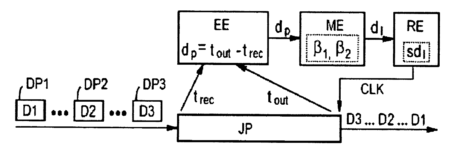
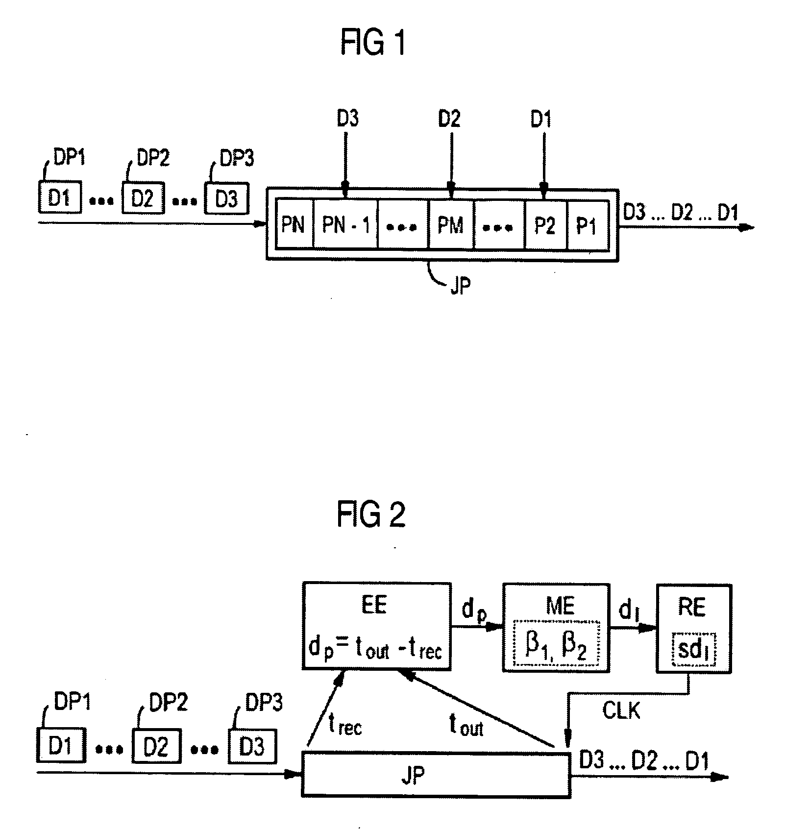
[0019] FIG. 1 is a schematic of a jitter buffer JP to which data packets DP1, . . . , DP2, . . . , DP3 of a preferably internet protocol based data packet stream, for example for real-time, voice, video and / or multimedia communication, are routed for buffering. Data packets DP1, . . . , DP2, . . . , DP3 in each case contain a timestamp indicating the original time position of the relevant data packet in the data packet stream. It is assumed in the present exemplary embodiment that data packets DP1, DP2, and DP3 were generated in the sequence indicated but that, owing to variations in propagation time, arrive at the jitter buffer JP in the sequence DP3, DP2, and DP1. Having been transmitted at above-average speed, data packet DP3 has thus overtaken data packet DP2, while data packet DP1, being particularly late, has fallen behind data packet DP2.

[0020] As useful data content, data packet DP1 contains communication data D1, data packet DP2 contains communication data D2, and data pack...


PUM


Abstract

Transmission delays due to the buffering of data packets are registered for the purpose of regulating a jitter buffer. Weighted mean delay values are continuously derived from registered transmission delays, with a shorter transmission delay receiving a higher weighting than a longer transmission delay. A read-out speed of the jitter buffer is then regulated as a function of the continuously derived weighted mean delay values in such a way that the weighted mean delay values are adjusted as a regulating variable to a predefined desired delay.

Description

[0001] This application claims priority to the German application No. 10312438.1 DE, filed Mar. 20, 2003 and which is incorporated by reference herein in its entirety.[0002] In modern communication systems, connections for transmitting continuous data streams, as employed, for instance, for voice, video, and / or multimedia communication, are increasingly also being routed over packet oriented communication networks, such as LANs (Local Area Network), MANs (Metropolitan Area Network), and WANs (Wide Area Network). This technology forms the basis of, for example, what is called internet telephony, frequently also referred to as "Voiceover-Internet Protocol" (VoIP).BACKGROUND OF INVENTION[0003] To transmit a continuous data stream over a packet-oriented communication network, the data stream is first split into data packets for individual transmission which are each provided with a destination address and a timestamp. On exiting the packet-oriented communication network the data packets...

Claims


Application Information

Patent Timeline
Patent Type & Authority Applications(United States)
IPC IPC(8): H04L47/30
CPCH04L47/10H04L47/30H04L47/28
Inventor BAUER, WOLFGANGFALLY, GERHARD
Owner UNIFY GMBH & CO KG
Why Eureka
Try Eureka