
Utility scaffolding having safety features

Inactive Publication Date: 2004-09-30
WYSE STEVEN J
View PDF3 Cites 17 Cited by
  • Summary
  • Abstract
  • Description
  • Claims
  • Application Information

AI Technical Summary

Benefits of technology

[0010] The present invention solves the above-described and other problems and provides a distinct advance in the art of safe scaffolding. More particularly, the present invention provides features which may be used in combination or independently to more safely and securely couple scaffolding members, including coupling the braces to the legs and the platform to the beams.
[0013] The third and fourth features act to prevent inadvertent movement of the platform relative to the beams. The third feature provides platform pins welded or otherwise secured to the beams and rising upwardly therefrom to fit into pin holes drilled into the platform. Once the platform pins are received within the pin holes, the platform is prevented from shifting horizontally off of the beams. The fourth feature provides spring-biased C-clips operable to engage the beams and platform so as to prevent relative vertical movement therebetween and ensure that the platform will not inadvertently lift off the platform pins due, for example, to warping or vibration.

Problems solved by technology

Unfortunately, in providing quickly connectable / disconnectable scaffolding assembly mechanisms, many existing scaffolding systems sacrifice safety and are prone to inadvertent and unsafe disassembly potentially resulting in damage or injury.
One disadvantage of the L-pin design is that it presents a projecting handle portion prone to catching on passing objects which can cause the L-pin to be inadvertently removed from the holes, thereby uncoupling the brace from the leg.
Furthermore, the platforms are typically unsecured on the beams, relying only on contact with a beam lip to remain in place.
Where platforms are warped or otherwise damaged, or are improperly placed upon the beams, they are prone to inadvertently slipping off the scaffolding.

Method used


Image

  • Utility scaffolding having safety features
  • Utility scaffolding having safety features
  • Utility scaffolding having safety features

Examples


Embodiment Construction

below.

[0015] A preferred embodiment of the present invention is described in detail below with reference to the attached drawing figures, wherein:

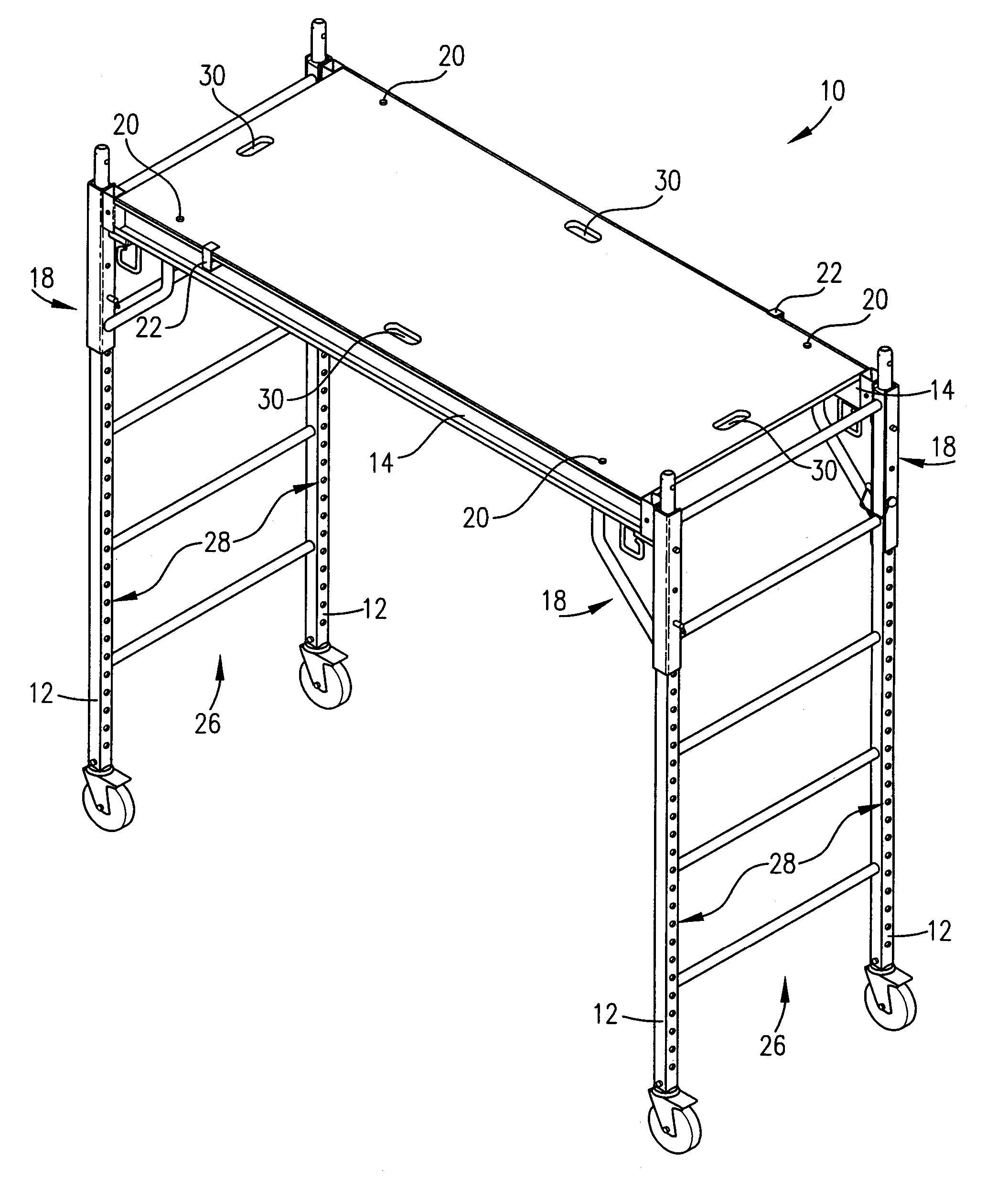
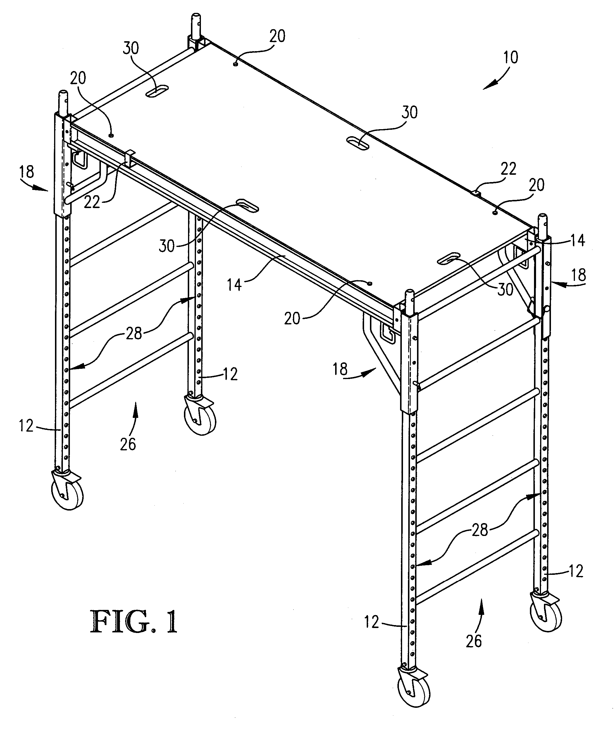
[0016] FIG. 1 is a perspective view of scaffolding incorporating preferred embodiments of the four safety features of the present invention;

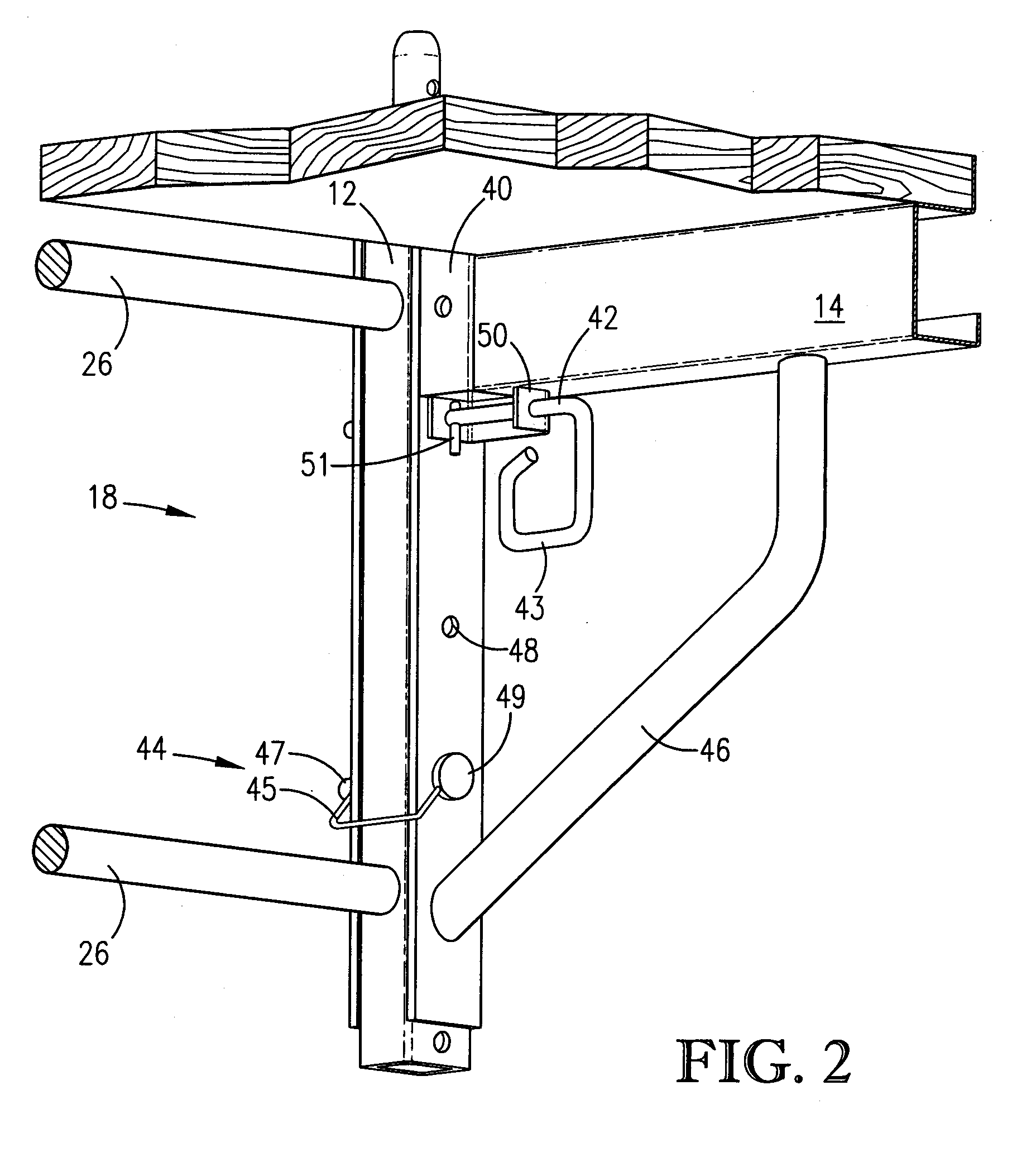
[0017] FIG. 2 is a fragmentary isometric view of a portion of the scaffolding of FIG. 1 showing in detail preferred embodiments of a first two of the safety features of the present invention; and

[0018] FIG. 3 is a sectional view of a portion of the scaffolding of FIG. 1 showing in detail preferred embodiments of a second two of the safety features of the present invention.

[0019] Referring to FIG. 1, scaffolding 10 is shown operable to provide an elevated work surface for one or more workers. It should be noted that the present invention is for safety features for securely coupling scaffolding structural members so as to permit quick and easy assembly and disassembly thereof while preventing potential e...


PUM


Abstract

Scaffolding (10) having safety features for coupling scaffolding structural members so as to prevent equipment damage and worker injury from inadvertent disassembly, while permitting quick assembly and disassembly when desired. The scaffolding (10) incorporating the safety features broadly comprises legs (12); beams (14); a platform (16); coupling braces (18); platform pins (20); and platform clips (22). The first safety feature is a rounded, spring-biased, rotation-limited G-pin for adjustably coupling the beams (14) with the legs (12). The G-pin's rounded shape and a perpendicularly projecting stop (51) minimize risks of inadvertent removal. The second feature is a lockable pin (44) operable to independently couple structural members (12,14) in the event the G-pin is inadvertently removed. The third and fourth features are platform pins (20) and spring-biased platform clips (22) operable to prevent, respectively, undesirable horizontal and vertical movement of the platform (16).

Description

[0001] This application is a continuation of application Ser. No. 10 / 065,251 filed on Sep. 27, 2003, which is a division of application Ser. No. 09 / 766,334 filed Jan. 19, 2001, now issued as U.S. Pat. No. 6,471,003 on Oct. 29, 2002, both of which are hereby by reference hereinBACKGROUND OF INVENTION[0002] 1. Field of the Invention[0003] The present invention relates to scaffolding for providing an elevated work surface. More particularly, the invention relates to safety features for securing assembled scaffolding to prevent inadvertent disassembly and potentially resulting damage and injury.[0004] 2. Description of the Prior Art[0005] Those ordinarily skilled in the art will appreciate that scaffolding is designed to be easily and quickly assembled where needed and disassembled for subsequent transport or storage. Unfortunately, in providing quickly connectable / disconnectable scaffolding assembly mechanisms, many existing scaffolding systems sacrifice safety and are prone to inadver...

Claims


Application Information

Patent Timeline
IPC IPC(8): E04G1/15E04G1/28E06C1/39E06C1/397
CPCE04G1/154E06C1/397E06C1/39E04G1/28E04G2001/242
Inventor WYSE, STEVEN J.
Owner WYSE STEVEN J
Learn More