Tool

a tool and tool body technology, applied in the field of tools, can solve the problems of very low noise development of the tool, and achieve the effects of different stroke lengths of the slave piston, low noise development of the tool, and favorable transmission ratio

Inactive Publication Date: 2005-06-16
ATLAS COPCO ELECTRIC TOOLS
View PDF8 Cites 3 Cited by
  • Summary
  • Abstract
  • Description
  • Claims
  • Application Information

AI Technical Summary

Benefits of technology

[0006] By using a piezo actuator as a drive unit, the masses to be moved can be kept small so that hardly any vibrations and noises are generated. At the same time, by controlling the piezo actuator the stroke length as well as the temporal course of the stroke of the oscillating movement can be adjusted freely for the most part. Coupling the piezo actuator to an adjusting travel enlarger enables the conversion of the minimal stroke length that is achieved by a piezo actuator into the stroke length range that is required for electrically operated tools. The adjusting travel enlarger effects in this connection the increase of the adjusting travel to a multiple of the original travel. By means of the piezo actuator, stroke frequencies of approximately 100 Hz, as conventional in regard to electric tools, can be easily achieved. At the same time, forces of a few 100 N and strokes of approximately 20 mm can be realized. By a suitable control of the piezo actuator, the frequency of the oscillating movement as well as the stroke length can be changed in fractions of a second and can be adjusted to the respective application purpose. In addition, the time / travel profile can be varied. Because of the minimal number of movable parts, the noise development of the tool is very low.
[0007] The adjusting travel enlarger comprises a transducer or master piston that acts through at least one liquid-filled pressure chamber onto at least one slave piston. The adjusting travel enlarger configured in this way can be manufactured in a simple way and ensures at the same time a large stepping-up action of the adjusting travel from the transducer or master piston to the slave piston. At the same time, the number of movable parts is minimal so that wear of such an arrangement is minimal also. A simple embodiment results when the piezo actuator and the master piston are fixedly connected to one another. For a favorable transmission ratio of the adjusting travel, the pressure surface of the slave piston is expediently 0.2 percent to 20 percent, in particular, 1 percent to 10 percent of the pressure surface of the master piston
[0008] It can be advantageous for the pressure chamber to act on two slave pistons having different pressure surfaces. In this way, different stroke length of the slave piston can be realized. The two slave pistons are, in particular, coupled with one another so that a coupled movement of the tool insert can be performed. Also, coupling three or more slave pistons can be advantageous. By designing the pressure surfaces as well as the coupling device appropriately, very different movement courses can be obtained. In this connection, the slave pistons can be slanted in different directions relative to the longitudinal axis of the piezo actuator.

Problems solved by technology

Because of the minimal number of movable parts, the noise development of the tool is very low.

Method used


Image

  • Tool
  • Tool
  • Tool

Examples


Embodiment Construction

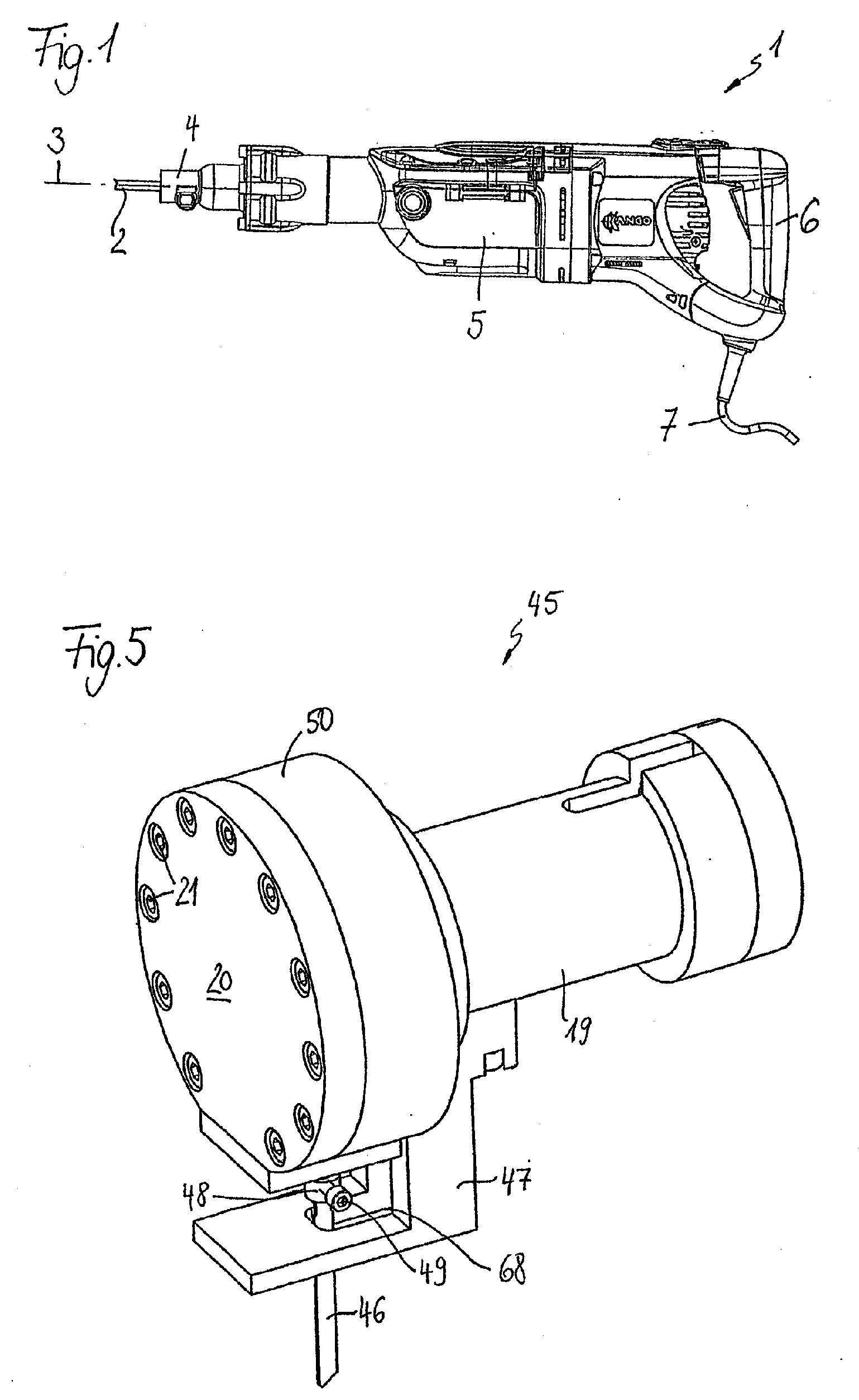
[0018] The drill and chisel hammer 1 illustrated in a side view in FIG. 1 has a tool insert 2 that is driven in rotation about its longitudinal axis 3 as well as oscillatingly in the direction of the longitudinal axis 3. The tool insert 2 is secured in a chuck 4 on the housing 5 of the drill and chisel hammer 1. An operating handle 6 is arranged on the housing 5. The drill and chisel hammer 1 is electrically driven. For supplying the electrical drive unit with electrical energy, a cable 7 is provided.

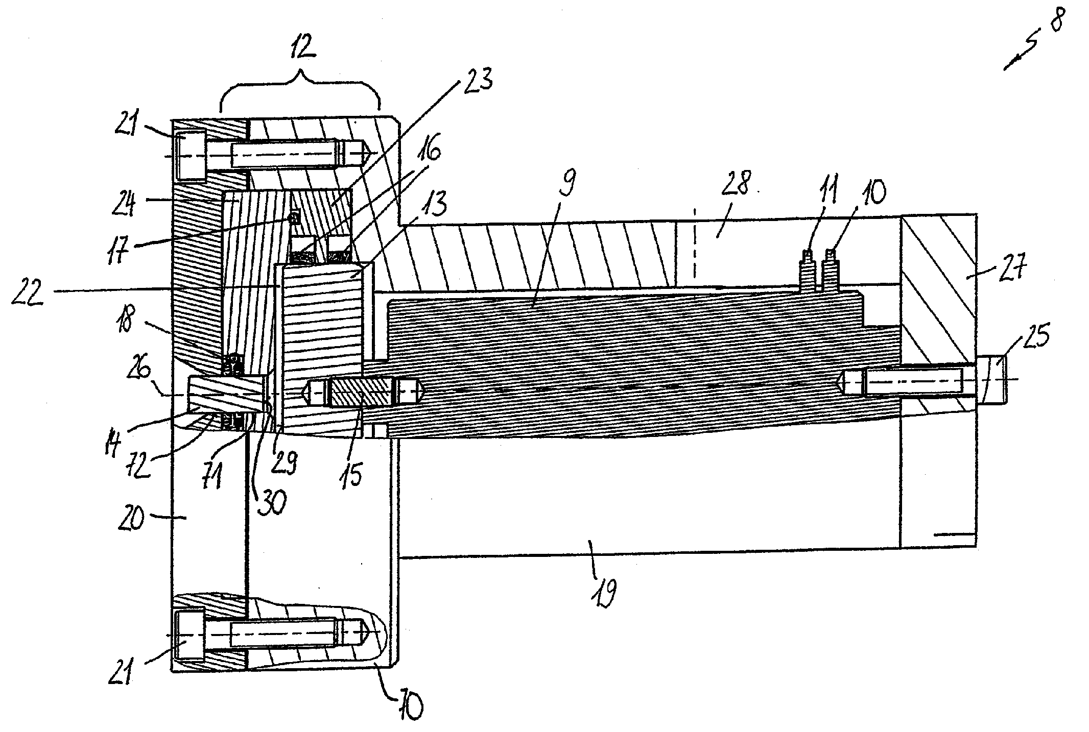
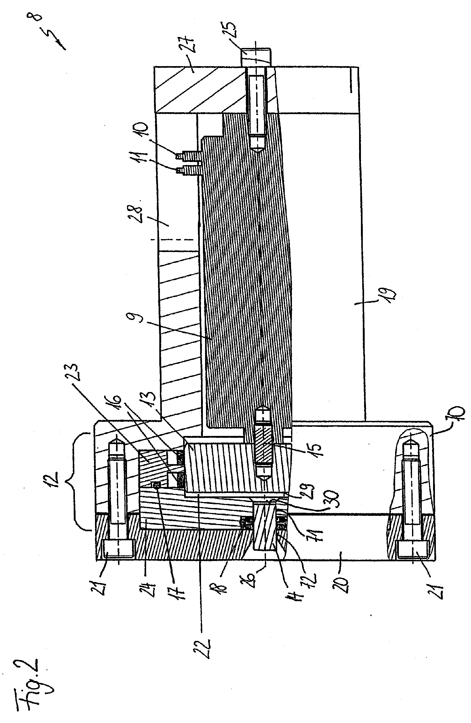
[0019] In FIG. 2, a drive unit 8 for oscillatingly driving the tool insert 2 in the direction of the longitudinal axis 3 is illustrated partially in section. For rotatingly driving the tool insert 2 about the longitudinal axis 3, an additional drive (not illustrated) is provided. The drive unit 8 comprises a piezo actuator 9 that is arranged in a housing 19 and also comprises an adjusting travel enlarger 12. The piezo actuator 9 is secured on the bottom 27 of the housing 19 by a fasten...


PUM

PropertyMeasurementUnit
thicknessaaaaaaaaaa
thicknessaaaaaaaaaa
stroke frequenciesaaaaaaaaaa

Abstract

A tool has a tool insert and an electrically operated drive unit oscillatingly driving the tool insert. The drive unit has a piezo actuator and an adjusting travel enlarger coupled to the piezo actuator. The adjusting travel enlarger has a master piston, at least one slave piston, and at least one pressure chamber. The master piston acts through the at least one pressure chamber on the at least one slave piston. The piezo actuator and the master piston are fixedly connected to one another.

Description

[0001] This is a continuation of International Application PCT / EP2002 / 009744 with an international filing date of Aug. 31, 2002, not published in English under PCT Article 21(2), and now abandoned. BACKGROUND OF THE INVENTION [0002] The invention relates to a tool, in particular a jigsaw, a saber saw, a drill or chisel hammer or the like, comprising a tool insert that is oscillatingly driven by an electrically operated drive unit. [0003] For driving oscillatingly a tool insert in a tool such as a jigsaw, a saber saw, a drill hammer or chisel hammer or the like, electric motors are used whose rotary movement is transformed mechanically, for example, by connecting links, into a translatory, oscillating movement of the tool insert. In this connection, the moved masses cause vibrations. At the same time, the noise development as a result of the moving parts is relatively high. The stroke length of the oscillating movement as well as the temporal course of the traveled distance are fixed...

Claims


Application Information

Patent Timeline
Patent Type & Authority Applications(United States)
IPC IPC(8): B23D51/16B23Q5/10B25D11/06B25D16/00H01L41/04H01L41/09H02N2/00
CPCB23D51/16B23Q5/10H02N2/043B25D16/00B25D11/064
Inventor HESS, ACHIM
Owner ATLAS COPCO ELECTRIC TOOLS
Why Eureka
Try Eureka