
Method of manufacturing a device, device manufactured thereby, computer program and lithographic apparatus

a technology of lithographic apparatus and manufacturing method, which is applied in the direction of electrical apparatus, printers, instruments, etc., can solve the problems of unsatisfactory effects, undesirable heating, and errors in the measurement of position

Active Publication Date: 2004-09-30
ASML NETHERLANDS BV
View PDF12 Cites 16 Cited by
  • Summary
  • Abstract
  • Description
  • Claims
  • Application Information

AI Technical Summary

Problems solved by technology

This can lead to undesirable effects such as variations in resist thickness at the edges, since the resist runs off more easily over the smooth unexposed areas, incorrect level measurements and / or undesirably abrupt leveling movements during a scan.
However, if exposures that overlap the edge of the substrate are carried out, the projection beam will fall on the substrate table leading to undesirable heating thereof.
Localized heating of the substrate table leading to thermal expansion can distort the mirrors and cause errors in the measurement of the position of the substrate table, leading to overlay errors in exposures.
The necessity to perform two exposures is an undesirable loss of throughput.
Thus structures in the transitional region will not be exposed properly and will likely tail off unpredictably rather than terminating cleanly.

Method used


Image

  • Method of manufacturing a device, device manufactured thereby, computer program and lithographic apparatus
  • Method of manufacturing a device, device manufactured thereby, computer program and lithographic apparatus
  • Method of manufacturing a device, device manufactured thereby, computer program and lithographic apparatus

Examples


Embodiment Construction

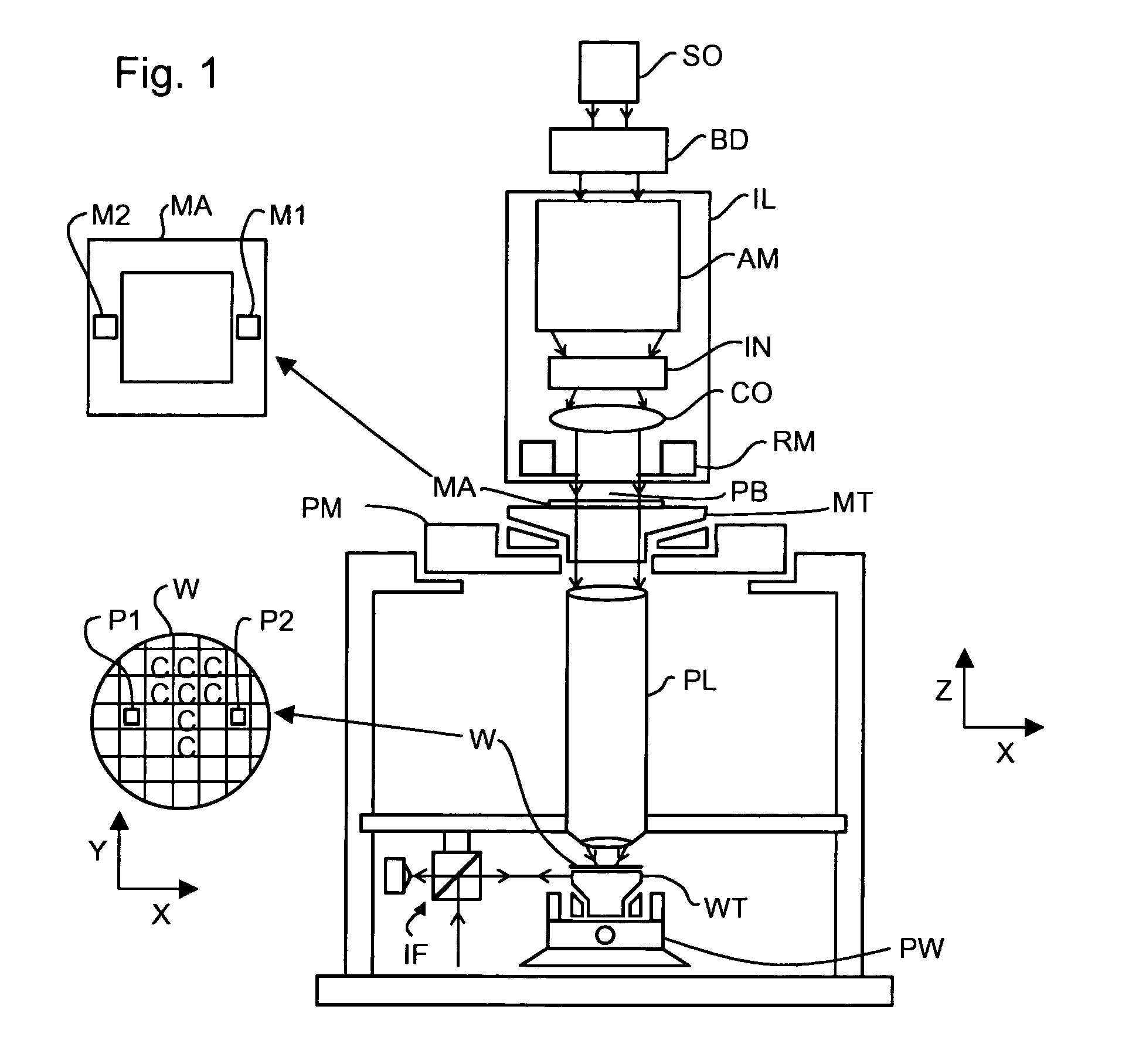
[0041] FIG. 1 schematically depicts a lithographic apparatus which may be used to perform methods of an embodiment of the invention. The apparatus comprises: an illumination system (illuminator) IL for providing a projection beam PB of radiation (e.g. UV radiation or DUV radiation); a first support structure (e.g. a mask table) MT for supporting patterning device (e.g. a mask) MA and connected to first positioning structure PM for accurately positioning the patterning device with respect to item PL; a substrate table (e.g. a wafer table) WT for holding a substrate (e.g. a resist-coated wafer) W and connected to second positioning structure PW for accurately positioning the substrate with respect to item PL; and a projection system (e.g. a refractive projection lens) PL for imaging a pattern imparted to the projection beam PB by patterning device MA onto a target portion C (e.g. comprising one or more dies) of the substrate W.

[0042] As here depicted, the apparatus is of a transmissiv...


PUM


Abstract

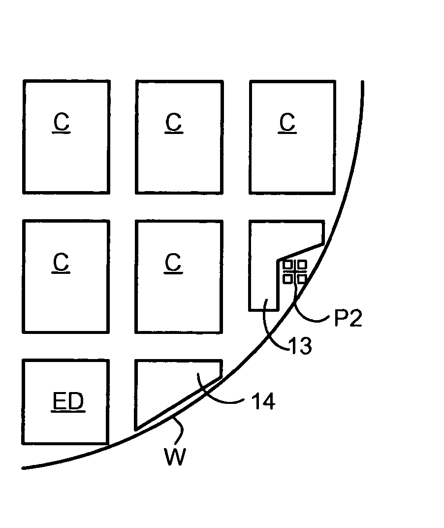
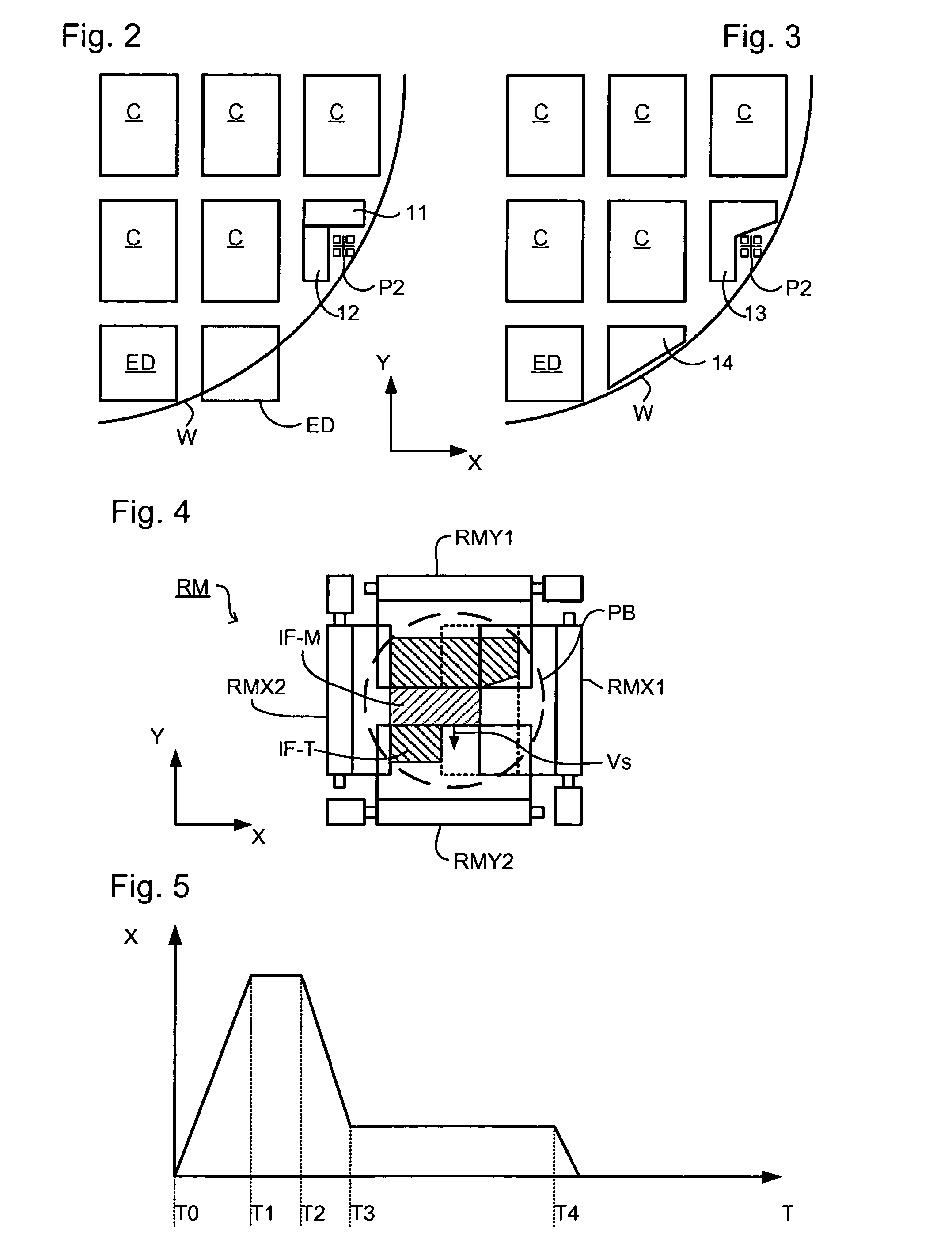
During scanned exposure of target portions at the edge of the substrate, the position of an edge of the illumination field is changed so as to prevent or reduce radiation falling onto the substrate table or to expose an L-shaped area. In this way the heat load on the substrate table can be reduced and dummy structures can fill a mouse bite without overlapping an alignment mark.

Description

[0001] The present application claims priority to European Application No. 02080451.4, filed on Dec. 19, 2002, the entirety of which is hereby incorporated into the present application by reference thereto.[0002] 1. Field of the Invention[0003] The present invention relates to a method of manufacturing a device, a device manufactured thereby, a computer program for controlling a lithographic apparatus, and a lithographic apparatus.[0004] 2. Brief Description of Related Art[0005] A lithographic apparatus is a machine that applies a desired pattern onto a target portion of a substrate. Lithographic apparatus can be used, for example, in the manufacture of integrated circuits (ICs). In that circumstance, a patterning device, such as a mask, may be used to generate a circuit pattern corresponding to an individual layer of the IC, and this pattern can be imaged onto a target portion (e.g. comprising part of, one or several dies) on a substrate (e.g. a silicon wafer) that has a layer of r...

Claims


Application Information

Patent Timeline
IPC IPC(8): G03F7/22G03F7/20H01L21/027
CPCG03F7/70066G03F7/70875G03F7/70358G03F7/70216H01L21/027
Inventor OTTENS, JOOST JEROENVAN KERVINCK, MARCEL NICOLAAS JACOBUS
Owner ASML NETHERLANDS BV
Learn More