Method of manufacturing structural components from tube blanks of variable wall thickness

a technology of variable wall thickness and structural components, which is applied in the direction of manufacturing tools, metal drawing, transportation and packaging, etc., can solve the problems of non-homogenous product, weak spots in formed products, and add a considerable amount to the total processing tim

Inactive Publication Date: 2004-10-14
ARCELORMITTAL TUBULAR PRODS CANADA
View PDF19 Cites 24 Cited by
  • Summary
  • Abstract
  • Description
  • Claims
  • Application Information

AI Technical Summary

Problems solved by technology

Although resulting in the required variable wall blank, and, therefore, formed product, this method includes various deficiencies.
Firstly, the method involves the pre-forming step of creating the multiwall blank using a welding procedure, which adds a considerable amount to the total processing time.
Secondly, the presence of welds may lead to weak spots in the formed product.
Although no welding steps are performed, this method results in a non-homogenous product.

Method used


Image

  • Method of manufacturing structural components from tube blanks of variable wall thickness
  • Method of manufacturing structural components from tube blanks of variable wall thickness
  • Method of manufacturing structural components from tube blanks of variable wall thickness

Examples


Embodiment Construction

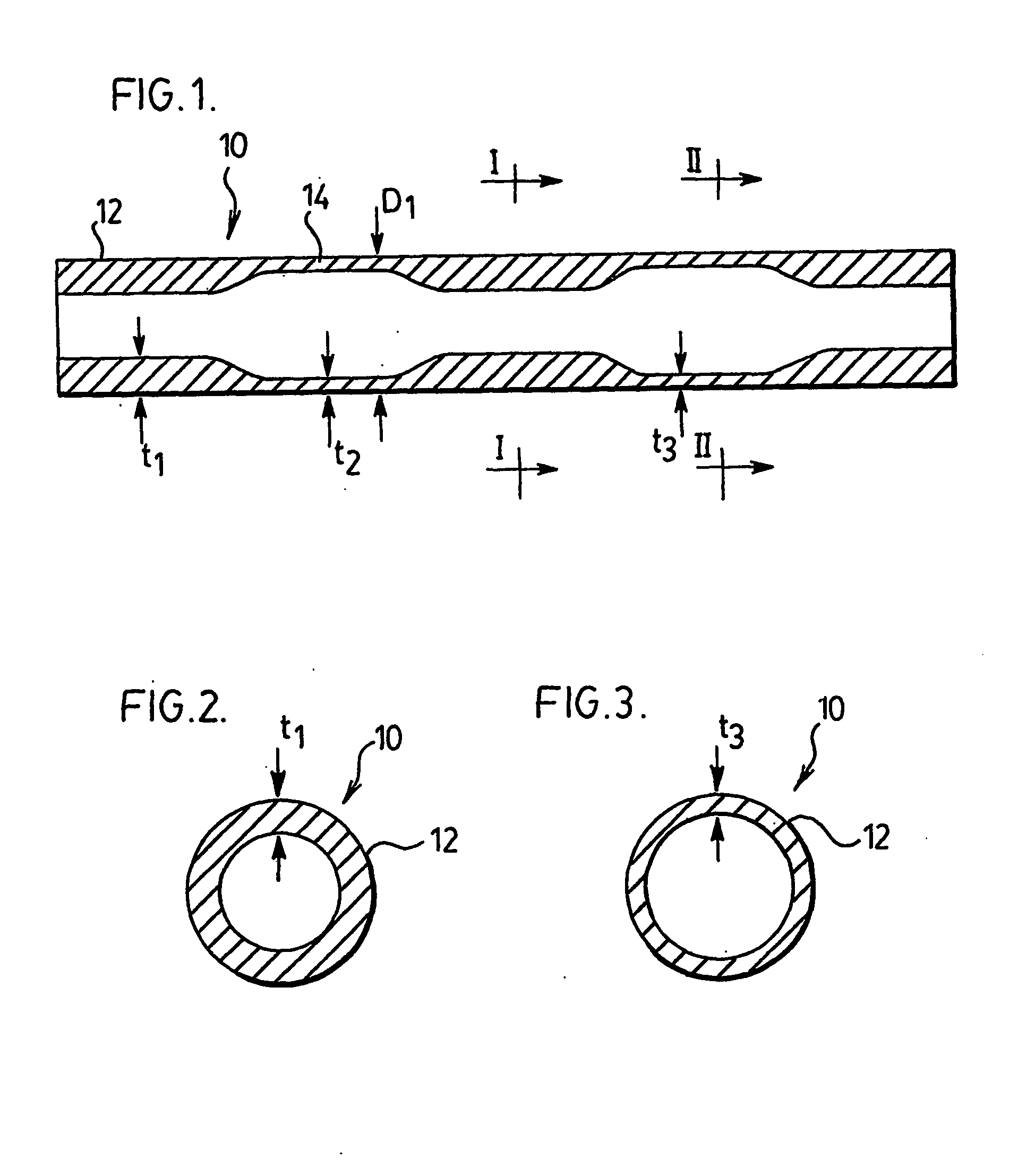
[0068] An example of a component manufactured according to the method of the invention is illustrate in FIGS. 8 to 13, wherein a vehicle axle is formed. In FIG. 8, a tube blank 60 is illustrated. The blank 60 has an outer surface 62 with a generally uniform outer diameter. The blank 60 is provided with 3 regions of reduced inner diameter, 64, 66 and 68, respectively. Accordingly, the blank 60 is thus provided with two regions, 70 and 72, of a larger inner diameter. Due to the constant outer diameter, the difference in inner diameter leads to different wall thicknesses in the regions 64 to 72. In the preferred embodiment, such differences in wall thickness are achieved by the reciprocating mandrel and die assembly discussed above. In the example shown in FIG. 8, the various regions are formed with wall thicknesses 74, 76, 78, 80 and 82 in the following dimensions:

1 Section Wall Thickness 74 3 mm 76 5 mm 78 3.4 mm 80 5 mm 82 3 mm

[0069] In the example of FIG. 8, the initial tube, prior...


PUM

PropertyMeasurementUnit
lengthaaaaaaaaaa
wall thicknessaaaaaaaaaa
thicknessaaaaaaaaaa

Abstract

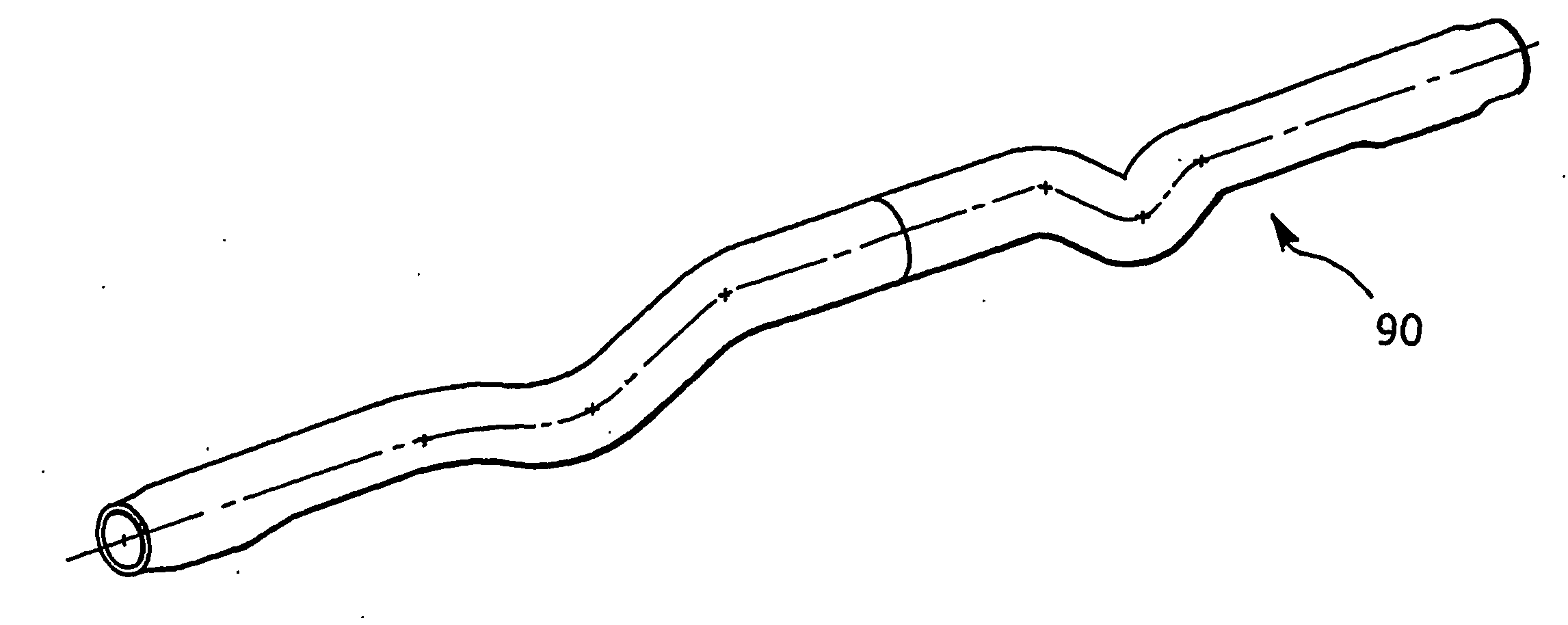
A method for forming a tubular structural member includes the steps of cold forming a tube blank (10) to have a longitudinally variable but circumferenfially constant wall thickness (t1, t2, t3) and forming the blank into the desired structural member (90). Preferably, the forming step involves hydroforming.

Description

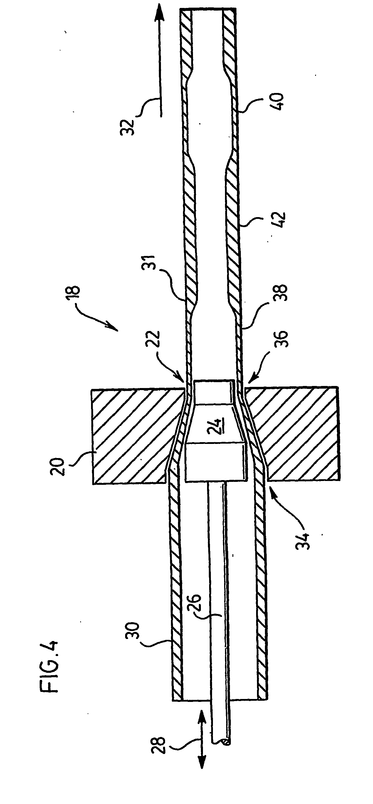
[0001] 1. Field of the Invention[0002] The present invention relates to a method of forming tube blanks to achieve a desired shape. Specifically, the method involves the forming of tube blanks that have a variable wall thickness. More specifically, the forming process comprises hydroforming.[0003] 2. Description of the Prior Art[0004] In the automotive industry, various structural components are made from tubular blanks. Such blanks are usually formed into the desired component shapes using various forming technologies. One of such techniques that has become popular is hydroforming. In hydroforming, a tubular blank is placed within a die having a shape of the desired component. The ends of the tube are sealed and a pressurized fluid is applied to the interior of the blank. Such pressure expands the blank until it conforms to the shape of the die cavity. In the usual case, prior to hydroforming, the tube blank is bent to the desired shape and the hydroforming step is used to provide ...

Claims


Application Information

Patent Timeline
Patent Type & Authority Applications(United States)
IPC IPC(8): B21D26/033B21D26/053B21D53/88
CPCB21C1/24B21C37/065B21C37/16B21D26/033B21D26/053B21D35/006B21D53/88
Inventor NEWPORT, COLINMCSWIGGAN, STEPHEN T.SAVESCU, OVIDIU I.
Owner ARCELORMITTAL TUBULAR PRODS CANADA
Why Eureka
Try Eureka