Congestion and delay handling in a packet data network

a packet data network and delay technology, applied in data switching networks, frequency-division multiplexes, instruments, etc., can solve the problems of slow response of tcp, congestion of links, and inability to apply the probabilistic view adopted by the red mechanism to this type of buffering problem, etc., to achieve low bandwidth, high latencies, and low bandwidth

Active Publication Date: 2004-11-04
TELEFON AB LM ERICSSON (PUBL)
View PDF5 Cites 162 Cited by
  • Summary
  • Abstract
  • Description
  • Claims
  • Application Information

AI Technical Summary

Problems solved by technology

Low bandwidth implies that one or at most a few TCP connections may congest the link.
High latency means that TCP will respond slowly when data packets are discarded.
The probabilistic view adopted by the RED mechanism is not easily applied to this type of buffering problem.
However, for low capacity links, the queue level may build up very quickly relative to the buffer size.
1) The use of a low pass filter in measuring queue size causes a delay in providing congestion feedback to the TCP sender(s);
2) The probabilistic way of discarding packets, which means that several packets may be accepted into the queue after congestion is detected but before the congestion is notified to the sender.

Method used


Image

  • Congestion and delay handling in a packet data network
  • Congestion and delay handling in a packet data network
  • Congestion and delay handling in a packet data network

Examples


Embodiment Construction

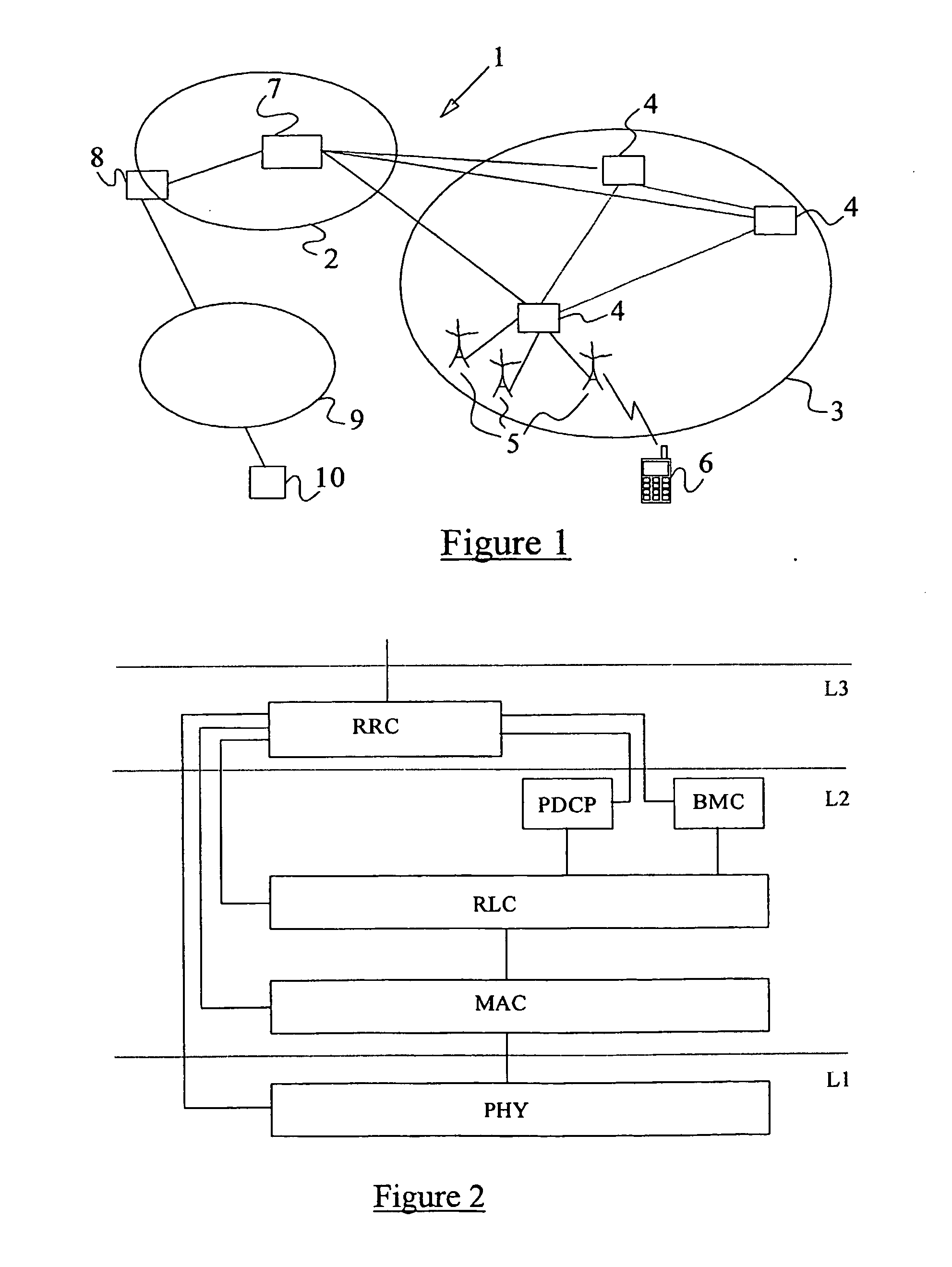
[0097] FIG. 1 illustrates schematically a UMTS network 1 which comprises a core network 2 and a UMTS Terrestrial Radio Access Network (UTRAN) 3. The UTRAN 3 comprises a number of Radio Network Controllers (RNCs) 4, each of which is coupled to a set of neighbouring Base Transceiver Stations (BTSs) 5. BTSs are sometimes referred to as Node Bs. Each Node B 5 is responsible for a given geographical cell and the controlling RNC 4 is responsible for routing user and signalling data between that Node B 5 and the core network 2. All of the RNCs are coupled to one another. A general outline of the UTRAN 3 is given in Technical Specification TS 25.401 V3.2.0 of the 3rd Generation Partnership Project. FIG. 1 also illustrates a mobile terminal or User Equipment (UE) 6, a Serving GPRS Support Node (SGSN) 7 and a GPRS Gateway Support Node (GGSN) 8. The SGSN 7 and the GGSN 8 provide packet switched data services to the UE 6 via the UTRAN (with the GGSN being coupled to the Internet 9).

[0098] User ...


PUM


Abstract

A method of managing a data packet queue in a buffer associated with the radio layers of a wireless network, the buffer storing packets prior to their transmission over the radio interface. The method comprises defining minimum and maximum threshold levels for the packet queue, and for a data packet received by the buffer 1) performing a congestion avoidance procedure if the buffer queue exceeds said maximum threshold level, or 2) not performing said procedure if the buffer queue is less than said minimum threshold level, or 3) if the buffer queue lies between said maximum and minimum thresholds, performing said congestion avoidance procedure for said packet, and not performing the procedure for at least one or more subsequent packets.

Description

[0001] The present invention relates to the handling of congestion and delay in a packet data network and more particularly to the early detection of congestion and delay and the implementation of mechanisms for obviating the consequences of congestion and delay.BACKGROUND TO THE INVENTION[0002] In data packet based communication systems, i.e. in which information to be transmitted is divided into a plurality of packets and the individual packets are sent over a communication network, it is known to provide queue buffers at various points in the network. A buffer may be a sending or input buffer (i.e. a buffer for data packets that are to be sent over a link) or a receiving or output buffer (i.e. a buffer for data packets that have already been sent over a link).[0003] Packets for transporting data may also be called by any of a variety of names, such as protocol data packets, frames, segments, cells, etc., depending on the specific context, the specific protocol used, and certain o...

Claims


Application Information

Patent Timeline
Patent Type & Authority Applications(United States)
IPC IPC(8): H04L47/31H04L47/32H04W28/08H04W28/14
CPCH04L41/0896H04L41/142H04L41/5077H04L43/0864H04L43/16H04L47/10H04L47/14H04L47/193H04L47/26H04L47/29H04L47/31H04L47/32H04L49/90H04L49/9078H04L2012/5647H04L2012/5682H04W28/08H04W28/14H04L43/0829H04W28/0231H04W28/0284H04W8/04
Inventor SAGFORS, MATS
Owner TELEFON AB LM ERICSSON (PUBL)
Why Eureka
Try Eureka