
Mounting arrangement for plug-in modules

a plug-in module and mounting arrangement technology, applied in the direction of optical elements, coupling device connections, instruments, etc., can solve the problems of reliability problems and reliability disadvantages, and achieve the effect of simple solution and easy extraction of plug-in modules

Inactive Publication Date: 2004-11-04
AVAGO TECH INT SALES PTE LTD
View PDF6 Cites 78 Cited by
  • Summary
  • Abstract
  • Description
  • Claims
  • Application Information

AI Technical Summary

Benefits of technology

[0008] Another object of the invention is to provide a simple solution operable in connection with plug-in modules such as pluggable transceiver for optical transmission systems by permitting to unplug such modules from their mounting racks.
[0009] A further object of the invention is to provide a mounting arrangement wherein an operator can easily perform extraction of the plug-in module from the respective reception member.
[0010] A still further object of the invention is to provide a mounting arrangement wherein the locking / unlocking movement is produced directly by an operating member such as a bail-like operating member without requiring any other parts such as a springs to ensure the return movement of the de-latching part.
[0011] Still another further object of the invention is to provide the mounting arrangement wherein the moving parts that ensure the latching and de-latching actions are subjected to translation movements only without any deformation of the components involved.
[0012] The invention provides a simple solution to the problems and needs outlined in the foregoing.

Problems solved by technology

Such an approach has a basic disadvantage in that it may require appreciable deformation of parts that are exposed to breaking, which leads to problems in terms of reliability.
Again, such arrangements are disadvantageous in terms of reliability and may require additional parts such as a springs and the like.

Method used


Image

  • Mounting arrangement for plug-in modules
  • Mounting arrangement for plug-in modules
  • Mounting arrangement for plug-in modules

Examples


Embodiment Construction

[0019] Embodiments of a mounting arrangement and components thereof are described herein.

[0020] In the following description, numerous specific details are given to provide a thorough understanding of embodiments of the invention. One skilled in the relevant art will recognize, however, that the invention can be practiced without one or more the specific details or with other methods, components, materials and so on.

[0021] In other instances, well-known structures, materials, or operations are not shown or described in detail to avoid obscuring aspects of the invention.

[0022] Reference throughout this specification to "one embodiment" or "an embodiment" means that a particular feature, structure, or characteristic described in connection with the embodiment is included in at least one embodiment of the present invention. Thus, the appearances of the phrases "in one embodiment" or "in an embodiment" in various places throughout this specification are not necessary or referring to the...


PUM


Abstract

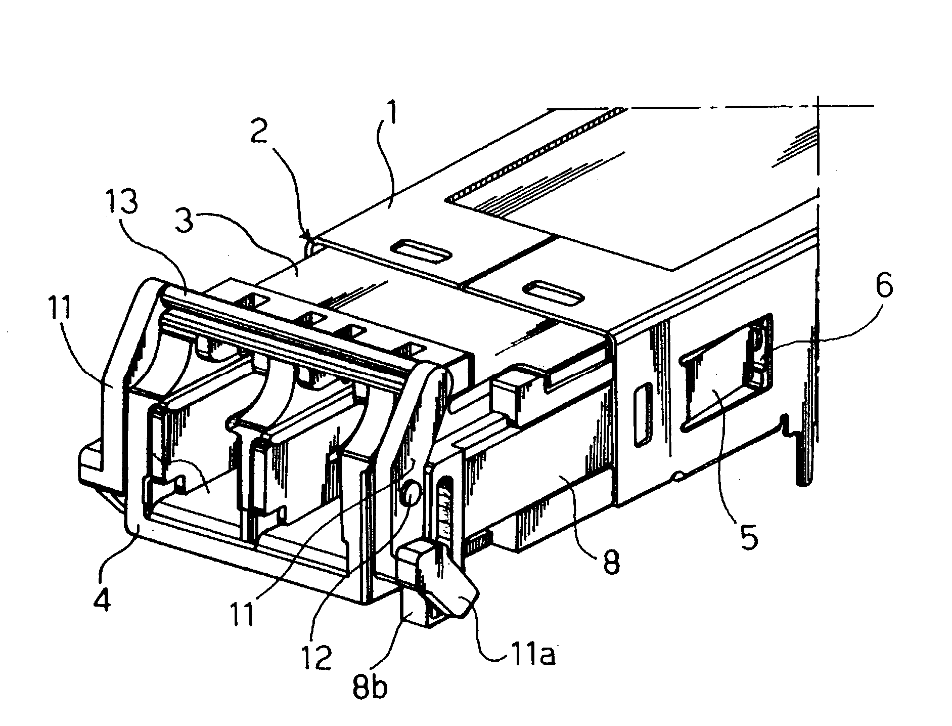
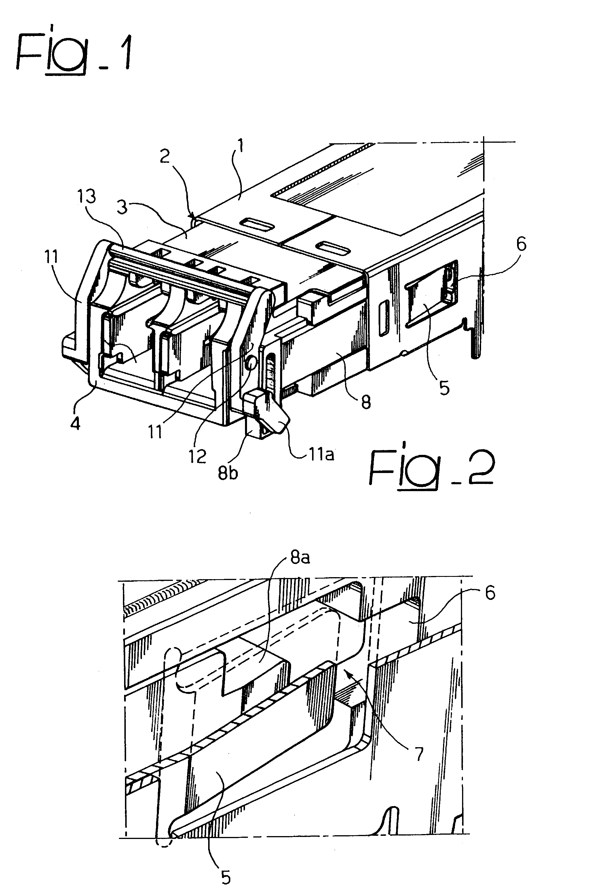
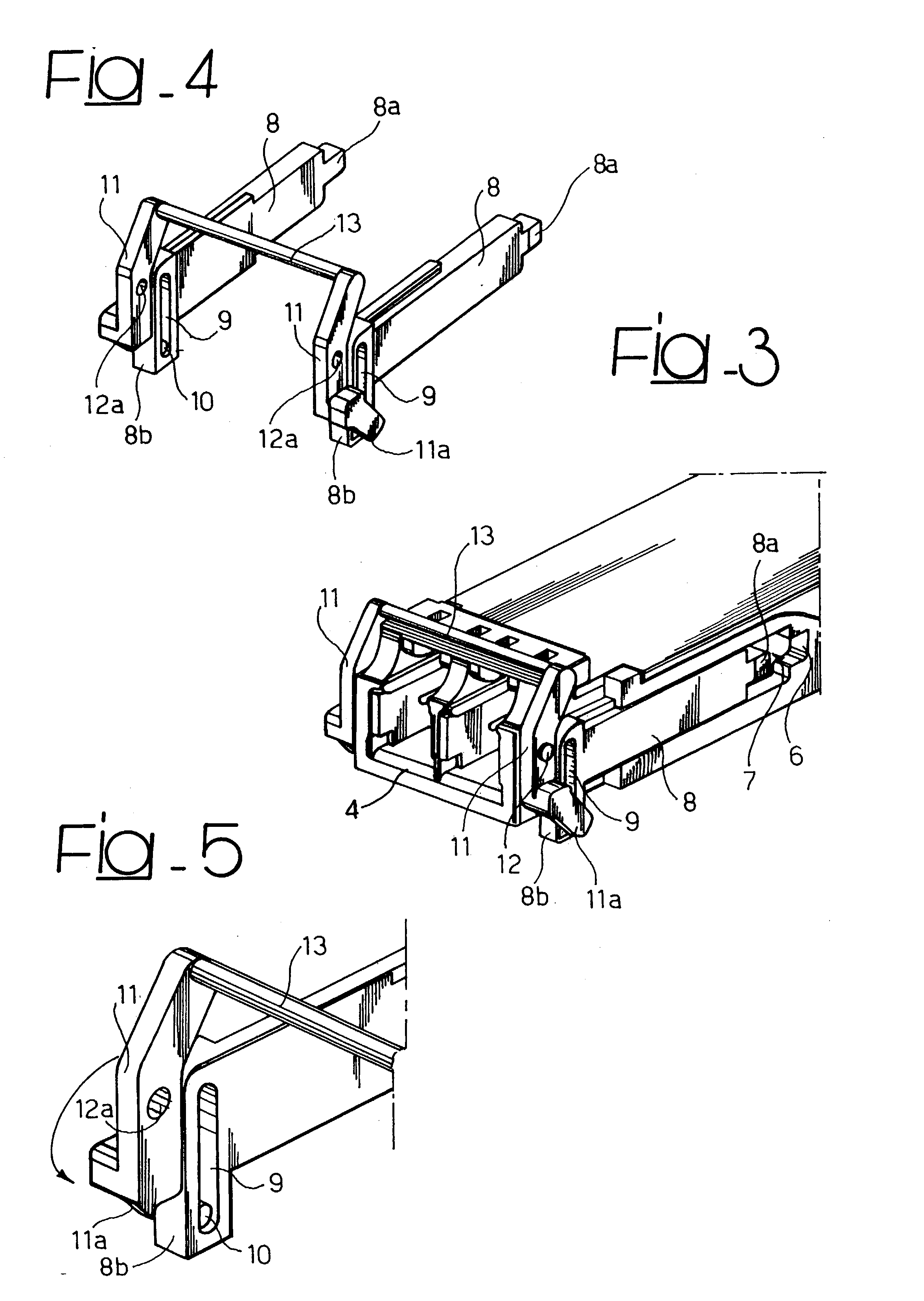
A plug-in module such as a transceiver for an optical communications system is adapted to be inserted into the front opening of a cage-like reception member and to slide into the reception member towards an end mounting position. The module comprises a latch mechanism for latching the plug-in module in the end mounting position in the reception member. The module includes a front face having opposite sides and the latch mechanism includes a pair of levers tiltably associated with the plug-in module at the opposite sides of the front face. The levers have homologous end portions with a transverse bar extending therebetween in a general bail-like fashion.

Description

[0001] The invention relates to mounting arrangements for plug-in modules.DESCRIPTION OF THE RELATED ART[0002] So-called "rack" mounting arrangements including a cage-like reception member and a plug-in module adapted to be inserted into the reception member and caused to slide into the reception member towards an end mounting position are currently used in many technical fields. Telecommunication equipment is an area exemplary of extensive use of such mounting arrangements.[0003] The plug-in module is retained (i.e. locked or latched) in its end mounting position, which typically occurs via resiliently biased members such as elastic finger formations and the like. In order to permit the plug-in module to be extracted from the reception member, the locking member(s) must be acted upon in order to disengage and release the plug-in module.[0004] In such arrangements, parts made of plastics or other materials are frequently used. These are intended to be deformed in order to lock or un...

Claims


Application Information

Patent Timeline
IPC IPC(8): G02B6/42H01R13/627H01R13/629
CPCG02B6/4292H01R13/6275H01R13/62905H01R13/62933
Inventor DI MASCIO, ENRICO
Owner AVAGO TECH INT SALES PTE LTD
Features
  • Generate Ideas
  • Intellectual Property
  • Life Sciences
  • Materials
  • Tech Scout
  • Unparalleled Data Quality
  • Higher Quality Content
  • 60% Fewer Hallucinations
Learn More