Rotor shaft bearing design and coupling mechanism

a technology of rotor shaft bearings and coupling mechanisms, which is applied in the direction of pump components, positive displacement liquid engines, liquid fuel engines, etc., can solve the problems of liquids that are not suitable for use, require more frequent maintenance, and receive undue wear from abrasive liquids, so as to improve the stability of the axial position of the rotor shaft

Active Publication Date: 2004-11-11
VIKING PUMP
View PDF7 Cites 15 Cited by
  • Summary
  • Abstract
  • Description
  • Claims
  • Application Information

AI Technical Summary

Benefits of technology

0025] FIG. 7 is a front plan view of a lock ring of the improved mechanism for coupling the inner magnet assembly to the rotor shaft and for improving the stability of the axial position of the rotor shaft of a magnetic drive pump in accordance with this disclosure;

Problems solved by technology

Further, the lack of bearing support at either the proximal end 39 or the distal end 48 of the rotor shaft 37 may be problematic in some designs resulting in the proximal end 39 and the distal end 48 of the shaft 37 being exposed to excessive frictional forces thereby requiring more frequent maintenance.
Still another problem associated with the design shown in FIG. 1 is the use of the pumped fluid as a coolant for the components disposed within the canister 44.
Further, if the fluid being pumped is extremely abrasive, such as a metal particulate slurry, damage to the inner magnet assembly 35 may occur as the canister 44 or cover 43 may receive undue wear from the abrasive liquid.
Finally, some liquids are not suitable for use as a coolant medium for the inner magnet assembly 35.

Method used


Image

  • Rotor shaft bearing design and coupling mechanism
  • Rotor shaft bearing design and coupling mechanism
  • Rotor shaft bearing design and coupling mechanism

Examples


embodiment 60

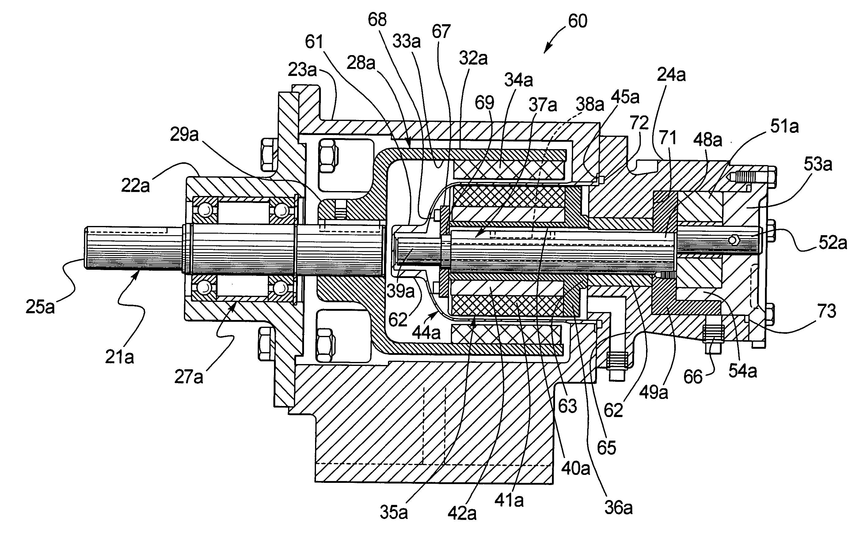
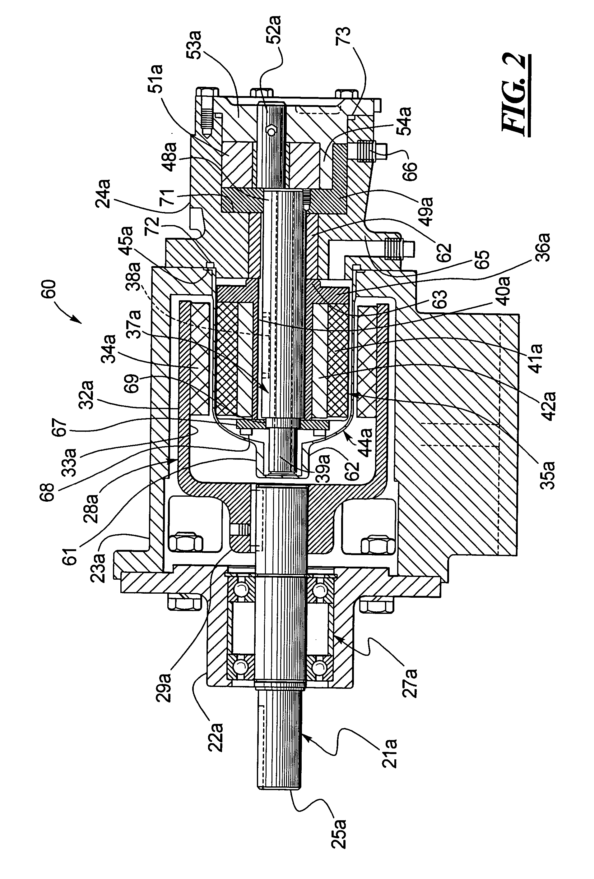
[0038] In the embodiment 60 shown in FIG. 2, the axial position of the rotor shaft 37a is stabilized because the lock nut 67 is securely fastened to the inner magnet assembly 35a and axial movement of the inner magnet assembly 35a in a distal direction or towards the pump chamber is prevented by engagement of the annular flange 63 against the distal bushing 62. Further, axial movement of the rotor shaft 37a in a proximal direction, or towards the proximal end 62 of the can 44a is prevented by engagement of the rotor 49a against the distal bushing 62 or against the proximal wall 71 of the pump chamber that is defined by the casing 24a and head 53a.

[0039] Referring to FIG. 3 inlet and outlet ports are shown at 55a. Returning to FIG. 2, an o-ring for sealing the connection between the casing 24a and the coupling bracket 23a is shown at 72 while an o-ring for sealing the connection between the casing 24a and the head 53a is shown at 73.

[0040] Turning to FIG. 4, another embodiment of a m...

embodiment 100

[0048] Turning to FIG. 14, another embodiment 100 is disclosed which differs from the embodiment in FIG. 4. Specifically, referring back to FIG. 4, the proximal and distal ends of the distal bushing 64b includes radial slot shown at 98 that permits the entry of fluid between the distal bushing 64b and the thrust washers 81, 83. However, as shown in FIG. 14, the slots 98 in FIG. 4 have been eliminated so that a seal is provided between the distal bushing 64c, distal thrust washer 83c and proximal thrust washer 81c. Providing a seal on either side of the distal bushing 64c enables the pump chamber to be isolated from the axial passage through the casing in which the distal bushing 64c is accommodated. Further, the axial passageway 56b through the rotor shaft 37b has been eliminated.

[0049] Thus, instead of using the fluid being pumped through the pump chamber defined by the casing 24c and head 53c as a coolant medium for the interior of the can 44c, separate inlet and outlet ports are ...


PUM


Abstract

An improved magnetic drive pump is disclosed with improved bearing support for the proximal and distal ends of the rotor shaft. Further, an improved mechanism to couple the inner magnet assembly to the rotor shaft is also disclosed. Finally a mechanism for sealing the pump chamber from the interior of the canister that surrounds the inner magnet assembly is disclosed which permits a separate supply of coolant to be used for cooling the inner magnet assembly and the proximal end of the rotor shaft wherein such a coolant is not the fluid being pumped in the pump chamber. The pump chamber is isolated from the interior of the canister.

Description

[0001] An improved magnetic drive pump is disclosed. More specifically, a magnetic drive pump is disclosed wherein bearing support for the rotor shaft is provided within the canister that houses the inner magnet assembly. Further, bearing support is also provided for the rotor shaft adjacent the rotor. Thus, bearing support is provided for the rotor shaft at a proximal end of the rotor shaft disposed within the canister and at a distal end of the rotor shaft disposed adjacent the rotor. Further, a mechanism for providing a seal to inhibit fluid migration from the pump chamber to this canister is also provided which permits a separate coolant fluid to be circulated within the canister in the event it is undesirable to use the fluid being pumped as a coolant fluid for the canister. Still further, an improved coupling mechanism for connecting the rotor shaft to the inner magnet assembly of a magnetic drive pump is also disclosed.[0002] Magnetic drive pumps have been employed which elim...

Claims


Application Information

Patent Timeline
Patent Type & Authority Applications(United States)
IPC IPC(8): F04C2/10F04C15/00
CPCF04C2/101F04C15/0069
Inventor MILLER, DALEMAYER, JIMREUTHER, JASON
Owner VIKING PUMP
Why Eureka
Try Eureka