Initiator assembly

a technology of initiator and assembly, which is applied in the direction of pedestrian/occupant safety arrangement, electric fuze, vehicular safety arrangement, etc., can solve the problems of large molding-shrinkage that a molding-shrinkage rate exceeds 1%, no improvement is considered concerning the reliability of operation, and the effect of forming a gap between

Inactive Publication Date: 2004-11-18
DAICEL CHEM IND LTD
View PDF6 Cites 39 Cited by
  • Summary
  • Abstract
  • Description
  • Claims
  • Application Information

AI Technical Summary

Benefits of technology

[0011] The protrusion is formed in an annular shape and / or a cylindrical shape to surround the electric type initiator, and it is formed on the metallic collar. As this protrusion, one or plural annular projections can be provided, or one or plural cylindrical projections can be provided or both an annular protrusion and a cylindrical protrusion can be provided. For example, when the metallic collar has an inner hole which the electroconductive pin of the electric type initiator passes through, the protrusion can be provided at a portion where the inner hole is formed. Also, the protrusion can be formed at an end surface of the metallic collar in a cylindrical shape to surround a periphery of the electric type initiator. In particular, the protrusion which is formed cylindrically is desirable, because a surface area of the protrusion can be obtained largely and a contacting area with resin can be made large enough.
[0032] Then, in a gas generator using this initiator assembly, since moisture cannot penetrate the inside of the initiator assembly, moisture-absorption and deterioration of a gas generating agent (a priming) can effectively be prevented, so that a gas generator which can maintain an original performance even after a long-term service can be obtained.

Problems solved by technology

However, in the initiator assembly disclosed in this publication, nothing is considered concerning improvement of the operation reliability in the initiator assembly itself and a secure actuation in the gas generator.
However, a resin with such a large molding-shrinkage that a molding-shrinkage rate exceeds 1% is undesirable because it is deformed, warped or obtains a shrink mark after solidification, and consequently, a gap may be formed between the electrical type initiator and the resin or between the metallic collar and the resin.

Method used


Image

  • Initiator assembly
  • Initiator assembly
  • Initiator assembly

Examples


embodiment 2

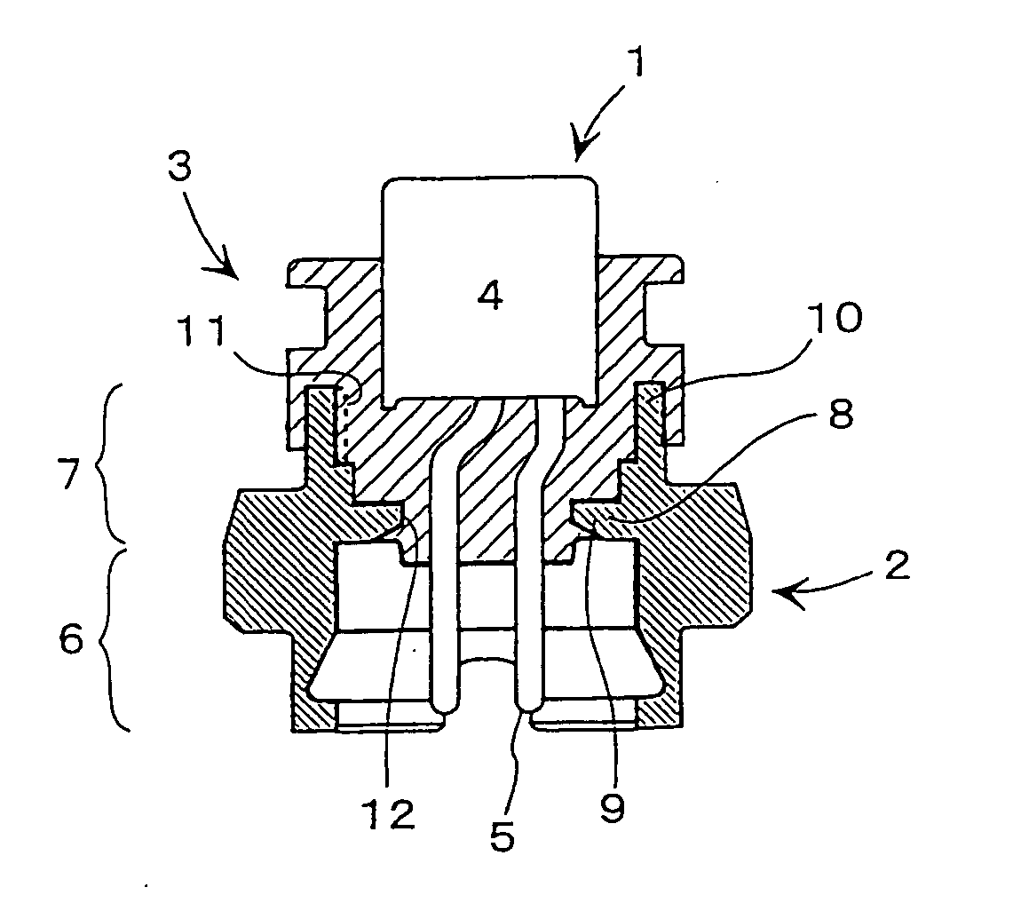
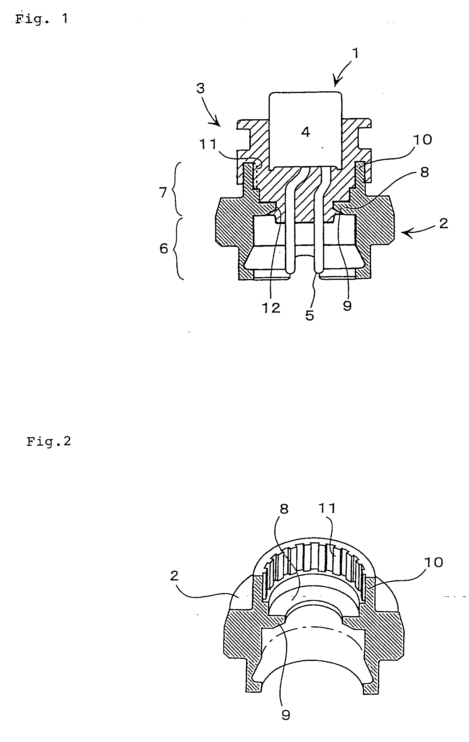
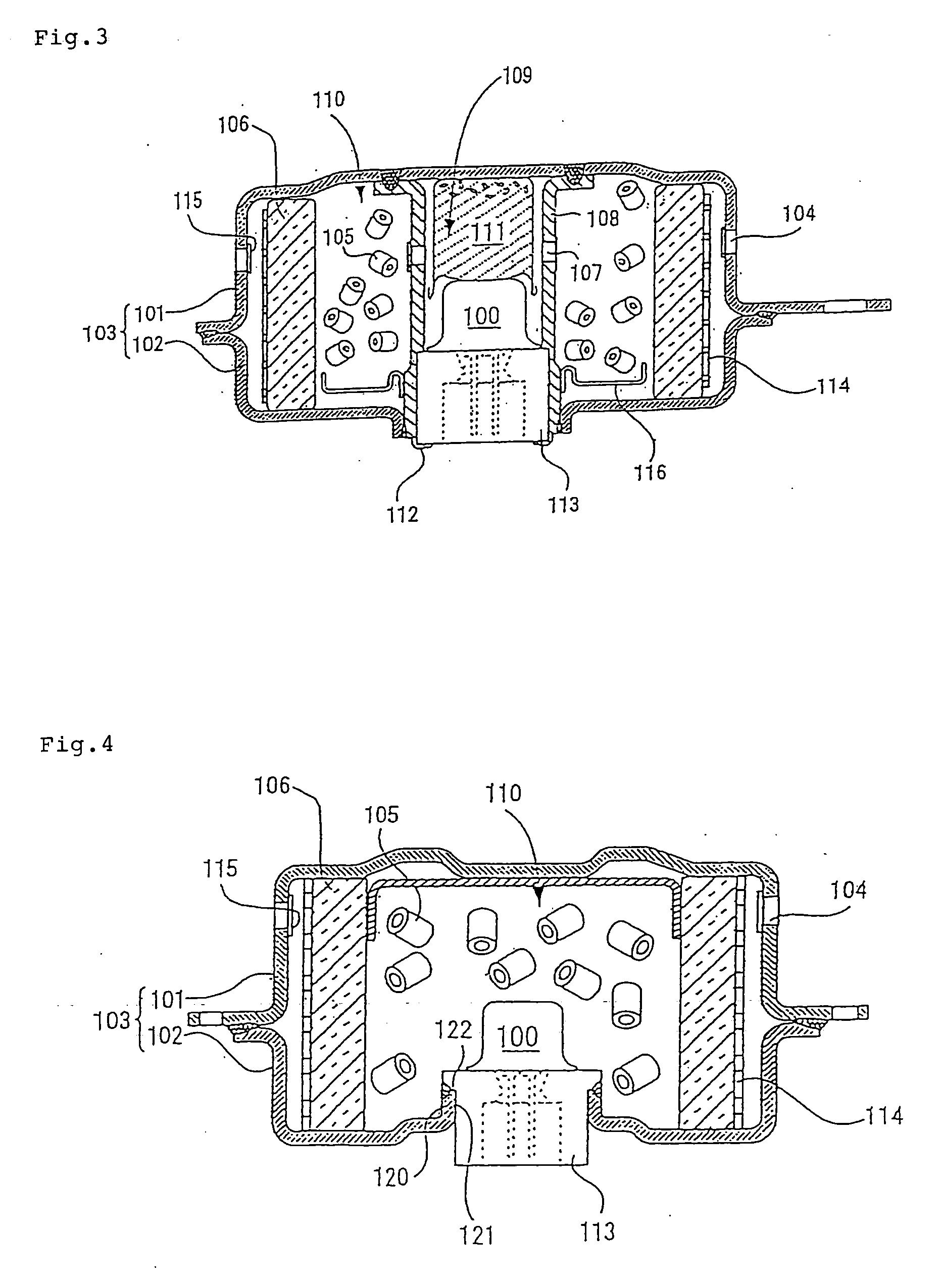
[0058] FIGS. 3 and 4 show embodiments of gas generators for air bags using an initiator assembly 100 having the same feature as the above-described initiator assembly.

[0059] The gas generator comprises, in a housing 103 formed by joining a diffuser shell 101 having a gas discharging port, and a closure shell 102 closing the diffuser shell, an ignition means including the above initiator assembly 100, a gas generating agent 105 to be ignited and burnt due to activation of the ignition means for generating a operating gas to inflate an air bag (bag body), and a filter means 106 to purify and / or cool a operating gas generated by combustion of the gas generating agent 105.

[0060] In the gas generator shown in FIG. 3, an inner cylindrical member 108 provided at its peripheral surface with a plurality of flame-transferring holes 107 is disposed at the center of the housing, a space 109 for accommodating the ignition means is formed inside the inner cylindrical member 108, and a combustion ...


PUM


Abstract

The present invention provides an initiator assembly in which a metallic collar and an electric type initiator are combined securely to block a moisture penetration into the inside of the gas generator, thereby obtaining operation reliability of the gas generator. An initiator assembly in which an electric type initiator and a metallic collar surrounding at least part of the electric type initiator are integrated with a resin, wherein at least either of an annular protrusion and a cylindrical protrusion provided in the direction to surround the electric type initiator is formed on the metallic collar, and the protrusion is covered with the resin.

Description

TECHNICAL FIELD TO WHICH THE INVENTION BELONGS[0001] The present invention relates to an initiator assembly used in various kinds of gas generators such as a gas generator for an air bag, a gas generator for a seatbelt pretensioner, a gas generator for a curtain air bag which are safety systems of motor vehicles, and more particularly, to an initiator assembly in which an electric type initiator to be actuated by an electrical signal and a metallic collar surrounding at least part of the electric type initiator are integrated with resin, a gas generator using this assembly, and a combied structure of a metallic collar and a resin in the initiator assembly.PRIOR ART[0002] An initiator assembly includes an electric type initiator to be actuated by an electrical signal from a collision detecting system, and it is mounted, interposing a metallic collar or the like, to various safety devices for a motor vehicle, such as a gas generator for an air bag, a gas generator for a seatbelt prete...

Claims


Application Information

Patent Timeline
Patent Type & Authority Applications(United States)
IPC IPC(8): B60R21/26B60R21/264F42B3/195
CPCB60R21/2644B60R2021/26029F42B3/195
Inventor ODA, SHINGO
Owner DAICEL CHEM IND LTD
Why Eureka
Try Eureka