Cell leakage monitoring circuit and monitoring method

a leakage monitoring and circuit technology, applied in the field of cell leakage monitoring circuit and monitoring method, can solve the problems of low leakage at the pn junction, difficult adjustment, difficult matching of pause refresh characteristics, etc., and achieve the effect of facilitating temperature compensation and period adjustmen

Inactive Publication Date: 2004-11-18
LONGITUDE SEMICON S A R L
View PDF2 Cites 10 Cited by
  • Summary
  • Abstract
  • Description
  • Claims
  • Application Information

AI Technical Summary

Benefits of technology

0024] Accordingly, it is an object of the present invention to provide a cell leakage monitor circuit and a cell leakage monitor method whereby temperature compensation and period adjustment may be facilitated.

Problems solved by technology

Moreover, the PN junction leakage is low in an amount of change dependent on bias-related temperature dependency to render temperature adjustment difficult.
Since the probability of the occurrence of tail bits in the DRAM is not larger than 0.01%, it is similarly difficult to effect matching to pause refresh characteristics.
Additionally, the leakage in the PN junction is low in temperature dependency, such that it is difficult to achieve effective temperature compensation.

Method used


Image

  • Cell leakage monitoring circuit and monitoring method
  • Cell leakage monitoring circuit and monitoring method
  • Cell leakage monitoring circuit and monitoring method

Examples


Embodiment Construction

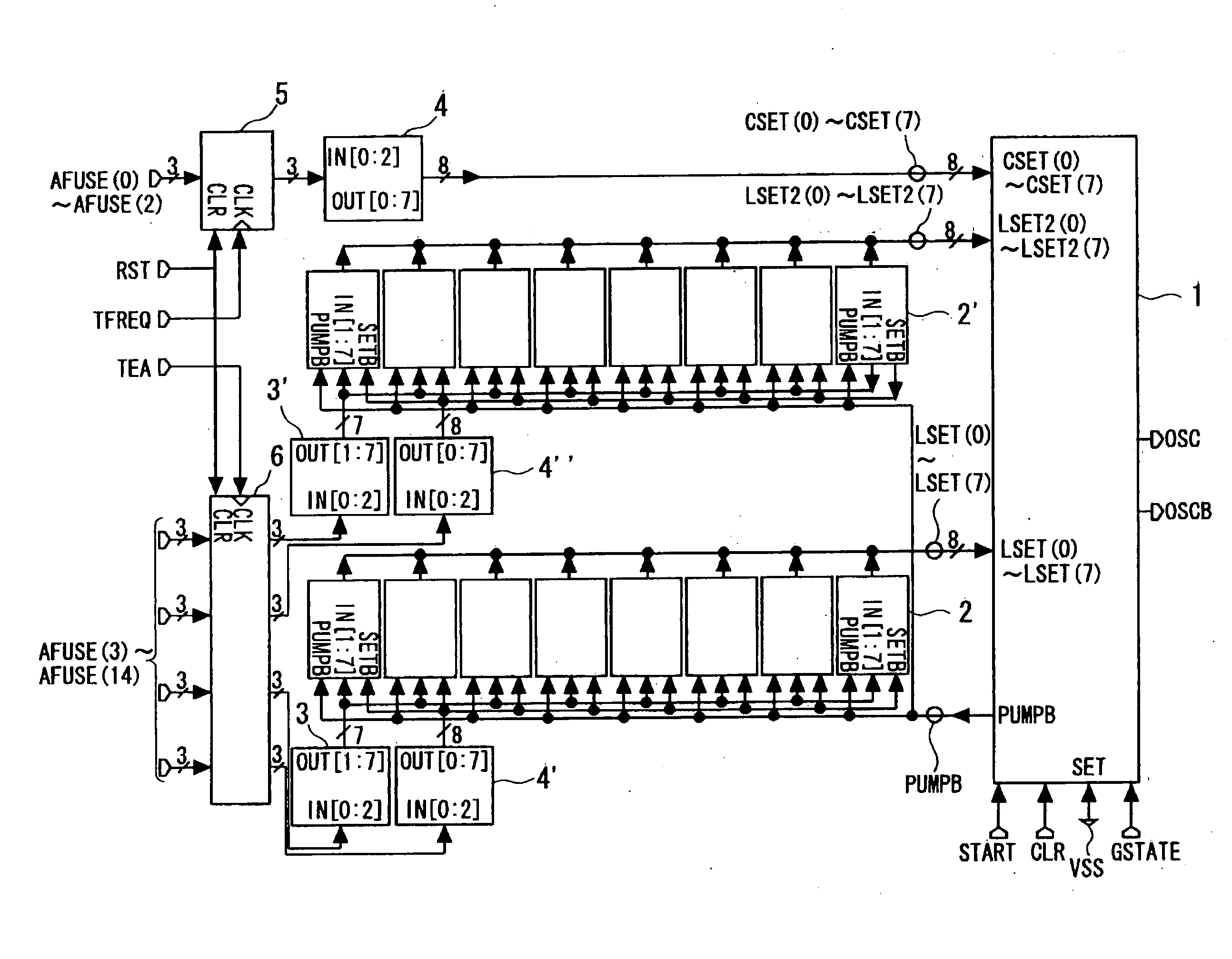
[0066] The present invention is now explained with reference to preferred embodiments thereof. First, the principle of the present invention is explained, and preferred embodiments thereof are then explained. In the present invention, the junction leakage gate end mode (akin to GIDL (gate induced drain leakage)), constitutes the pseudo-cell leakage source.

[0067] In an embodiment of the present invention, there are provided a capacitor selection circuit for adjusting the frequency (period) and a leakage source voltage generating circuit (voltage boost-up circuit) for adjusting the temperature dependency.

[0068] By controlling the gate voltage of the pMOSFET, it is possible not only to adjust the frequency (period) but also to control the temperature dependency.

[0069] In the present embodiment, the oscillator circuit of the self leakage monitor circuit activates and halts the refresh signal by a signal START from the refresh control circuit.

[0070] In the present embodiment, selection o...


PUM


Abstract

A cell leakage monitor includes a circuit for comparing the node voltage of a pseudo-cell equivalent to a memory cell of a DRAM to a reference value to output a refresh signal OSC when the node voltage of the pseudo cell has decreased to a reference value. As the leakage current, the GIDL (gate insulated drain leakage current) of a p-channel MOSFET is used. The cell leakage monitor also includes a circuit for selectively setting the gate voltage of the MOSFET of the leakage source and a circuit for selecting the capacitance value of the capacitor connected to the node voltage.

Description

[0001] This invention relates to a dynamic semiconductor storage device and, more particularly, to a circuit and a method for monitoring cell leakage.[0002] In a dynamic RAM (DRAM), the electric charge in an information storage capacitor in a memory cell leaks little by little, so that a refresh operation becomes necessary to perform. This refresh operation is usually carried out by evaluating the `real ability` (rate of capacitor leakage) of a large number of memory cells produced and by deciding on a refresh period with sufficient allowance so that the memory cell information will not be lost. However, if the refresh is carried out with a period with sufficient allowance, the number of the refresh cycles becomes larger than is necessary, and the throughput of the system employing the memory is lowered, while the power consumption during data hold time is also increased. Accordingly, there has been developed a memory device in which a number of memory cells equivalent to the memory...

Claims


Application Information

Patent Timeline
Patent Type & Authority Applications(United States)
IPC IPC(8): G11C11/406
CPCG11C11/406G11C11/40615G11C2211/4068
Inventor ITO, YUTAKA
Owner LONGITUDE SEMICON S A R L
Why Eureka
Try Eureka