Stereoscopic image picking up and display system

a stereoscopic image and display system technology, applied in optics, instruments, electrical equipment, etc., can solve the problems of not being able to obtain appropriate stereoscopic feeling, natural stereoscopic image cannot be obtained, and viewers cannot be satisfied

Inactive Publication Date: 2004-11-25
TOMITA TECH INT
View PDF1 Cites 161 Cited by
  • Summary
  • Abstract
  • Description
  • Claims
  • Application Information

AI Technical Summary

Problems solved by technology

In particular, when the same content are played back on display devices having different screen sizes, the stereopsis from the screen may vary due to difference in screen size since the amount of the parallax between the right-eye and the left-eye varies, resulting in a problem in that a natural stereoscopic image can not be obtained.
Since the stereoscopic image contents for large amusement parks are produced assuming that the display devices have a large size screen on which the contents are displayed, appropriate stereoscopic feeling can not obtained unless the displays have the same screen size.
Large size screen provides two strong stereoscopic feeling, making viewers uncomfortable, while small size screen provides less stereoscopic feeling, giving no satisfaction to the viewers.
Since these contents are combinations of various scenes, pick-up conditions, focal-length of the lens of the pick-up unit and the spacing between two pick-up units may not be uniform throughout various contents.
Furt

Method used


Image

  • Stereoscopic image picking up and display system
  • Stereoscopic image picking up and display system
  • Stereoscopic image picking up and display system

Examples


Embodiment Construction

[0083] Now, modes of embodying the present invention will be described with reference to the drawings.

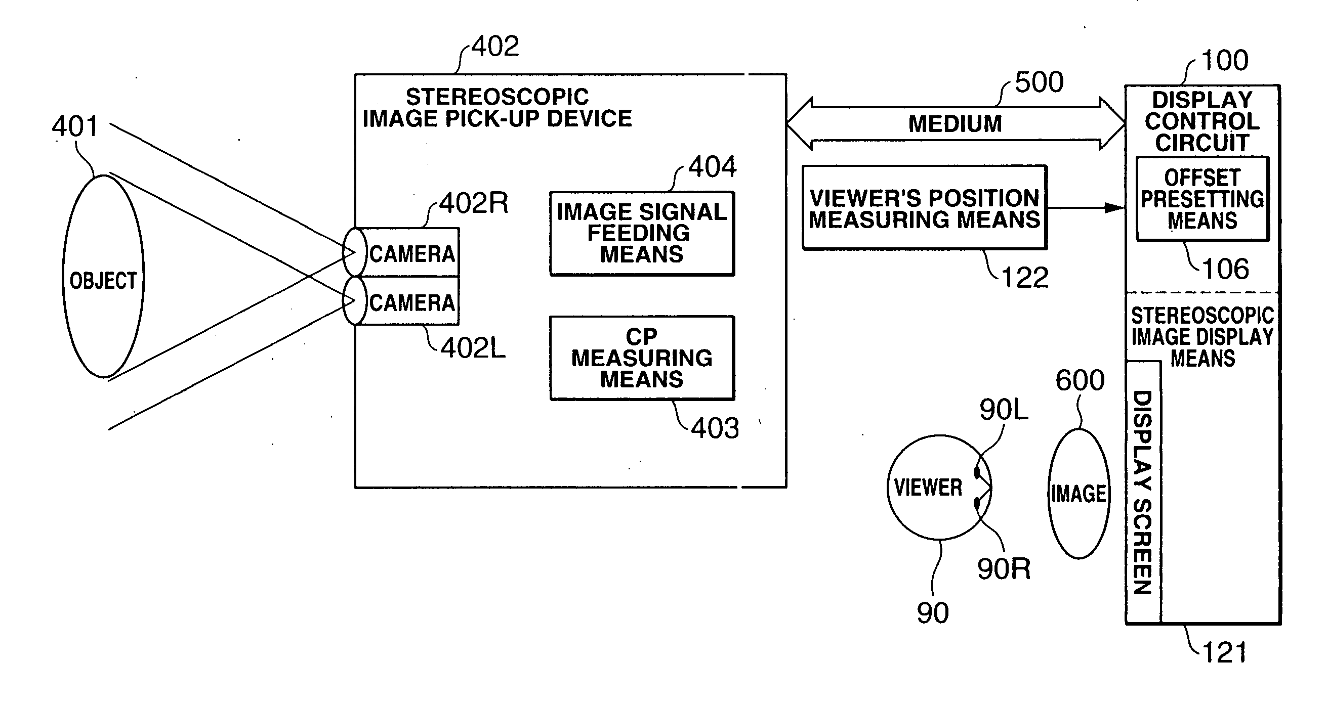
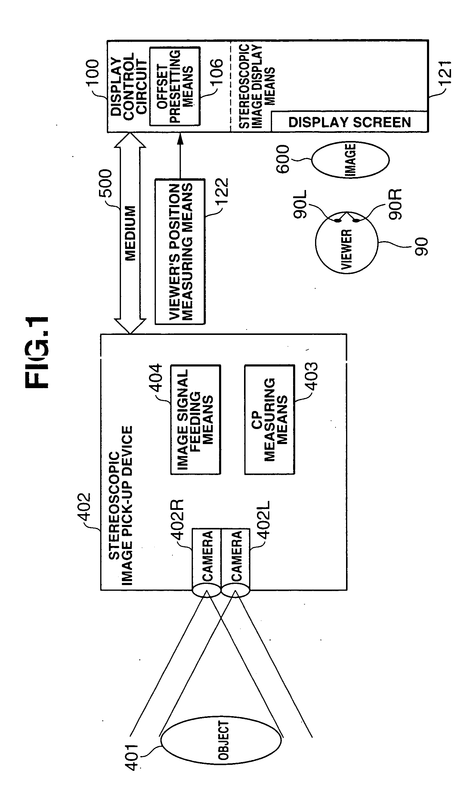
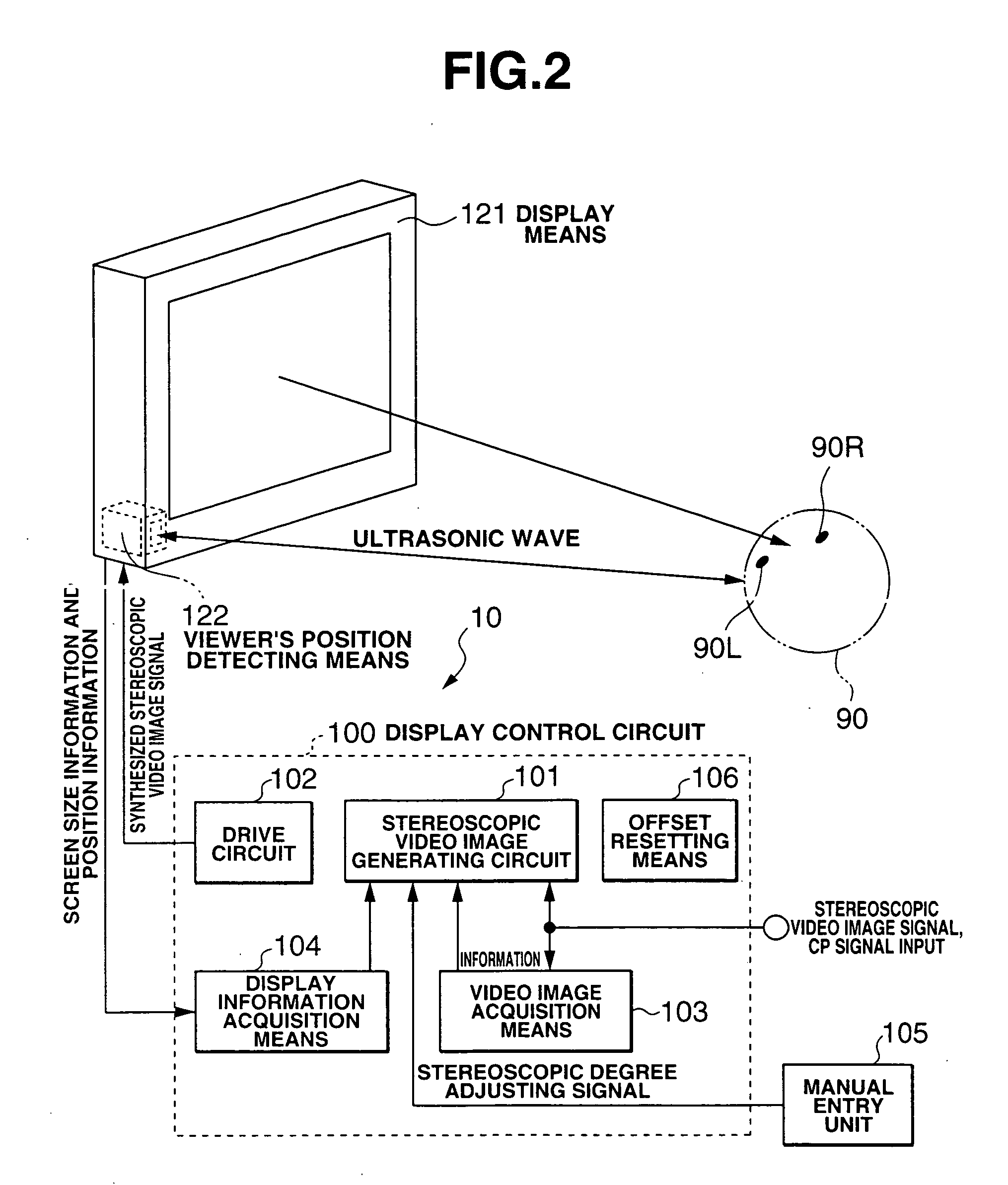
[0084] FIG. 1 is a block diagram for showing the basic configuration of the stereoscopic video image pick-up and display device of the present embodiment. FIG. 2 is a block diagram showing the configuration of the stereoscopic video image pick-up and display system shown in FIG. 1. FIG. 3 is a block diagram showing the display control circuit for the stereoscopic video image pick-up and display device shown in FIG. 1. FIGS. 4 through 6 are views showing how the stereoscopic image is viewed by a viewer. FIGS. 7 and 8 are views explaining the position at which the stereoscopic image appears. FIG. 0.9 is a view showing the configuration of the display means. FIG. 10 is an exploded perspective new showing the configuration of the display device in detail. FIG. 11 is a view showing the displaying state of the liquid crystal of the display device. FIG. 12 is a view showing the polarizatio...


PUM


Abstract

In a stereoscopic video image pick-up and display system comprising a stereoscopic video image pick-up device including two video image pick-up means (402R, L) for outputting video information from said pick-up means; a stereoscopic video image display device (400) for displaying different video images for the eyes of a viewer (60); and a medium (500) for transmitting said video image information from said stereoscopic video image pick-up device to said stereoscopic video image display device, said stereoscopic video image pick-up device includes cross-point measuring means (403) for measuring CP information on the cross-point (CP) of optical axes of said pick-up means and outputs information including the CP information and video image information to said medium, and said stereoscopic video image display device includes offset presetting means (106) for offsetting and displaying said different video images based upon said video image information, said cross-point information and information on the size of the image which is displayed by said stereoscopic video image display device.

Description

[0001] 1. Field of the Invention[0002] The present invention relates to a stereoscopic image pick-up and display system and in particular to a stereoscopic image pick-up and display system which is capable of displaying an appropriate stereoscopic images by changing the stereoscopic degree depending upon the size of a display screen and different stereoscopic image pick-up conditions.[0003] 2. Description of the Prior Art[0004] There have heretofore been stereoscopic image pick-up and display systems each comprising a stereoscopic image pick-up device, a stereoscopic image display device which displays the stereoscopic image which has been picked up by the stereoscopic image pick-up device and a medium which are disposed between both devices for transmitting image data and the like.[0005] For example, a stereoscopic image pick-up device which is disclosed in Japanese Published Patent Application JP-A-2001-231055 comprises a image pick-up unit 601 including two CCD cameras 602 and 60...

Claims


Application Information

Patent Timeline
IPC IPC(8): G02B27/00G02B30/25G02B30/26H04N13/00H04N13/04
CPCG02B27/0093G02B27/225G02B27/26H04N13/0022H04N13/0051H04N13/0434H04N13/0468H04N13/0497H04N13/337H04N13/167H04N13/366H04N13/128H04N13/398G02B30/26G02B30/25
Inventor TOMITA, SEIJIRO
Owner TOMITA TECH INT
Why Eureka
Try Eureka