
Method for controlling connections to a mobile station

a mobile station and connection technology, applied in the field of transmission link optimization, can solve the problems of increasing the load on the network, increasing the delay created by the link, and increasing the delay,

Inactive Publication Date: 2004-12-16
QUALCOMM INC
View PDF18 Cites 15 Cited by
  • Summary
  • Abstract
  • Description
  • Claims
  • Application Information

AI Technical Summary

Benefits of technology

[0010] A further object of the invention is to provide a method for reducing network load when a mobile station has moved from an area controlled by a first radio network controller to a second area controlled by a second radio network controller.

Problems solved by technology

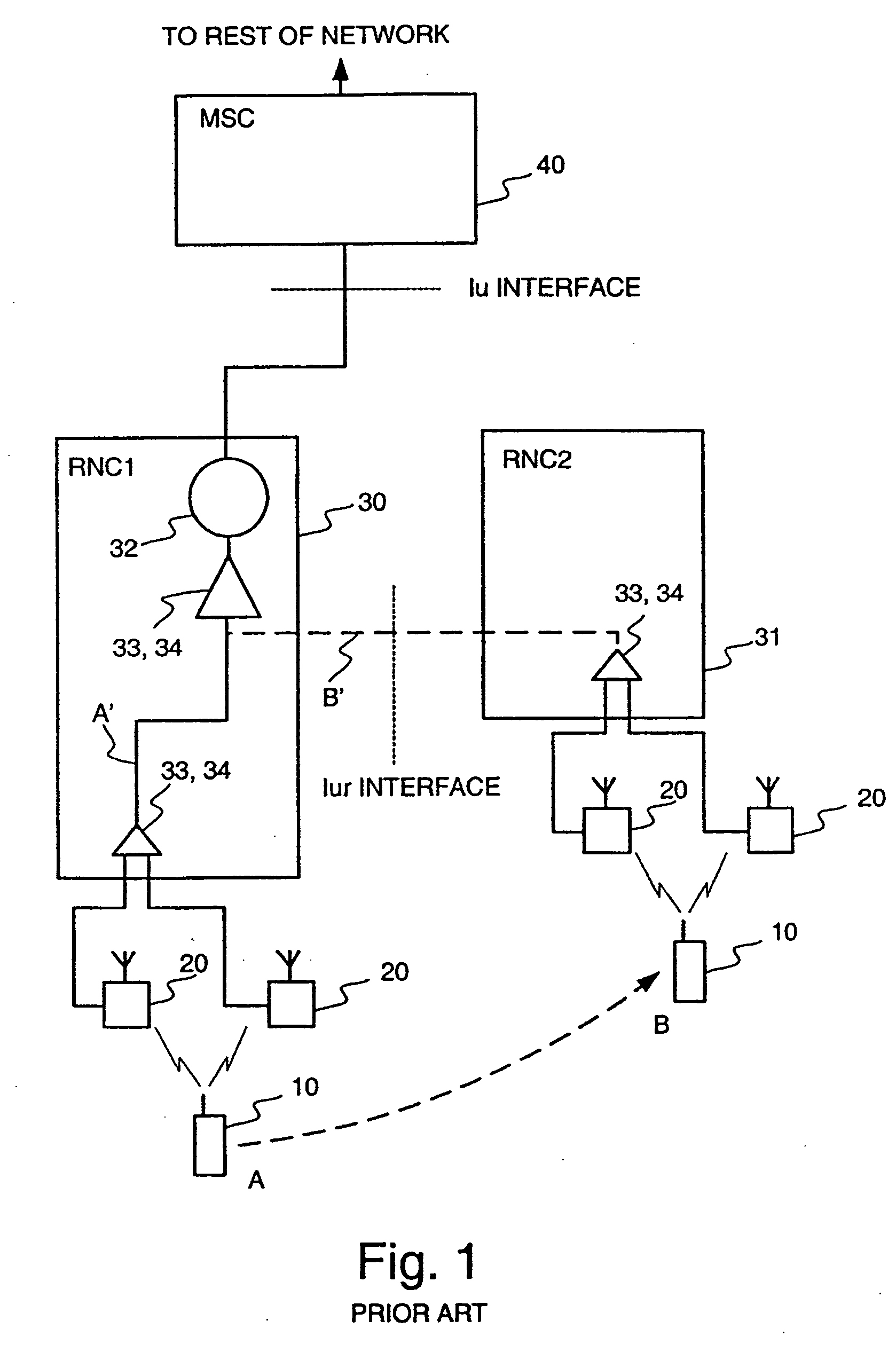
The system of FIG. 1, namely the use of a controlling RNC and a drift RNC, has certain drawbacks which arise from the fact that in situation B the transmission links are routed via two RNCs, instead of only one as in situation A. As the number of transmission links increase, the delays created by the links also increase.
The increase of delays places more demands on the whole network, when the network has to fulfill strict delay requirements for constant delay services, such as speech.
Further, since the number of transmission links in use increases, the load on the network increases.

Method used


Image

  • Method for controlling connections to a mobile station
  • Method for controlling connections to a mobile station
  • Method for controlling connections to a mobile station

Examples


Embodiment Construction

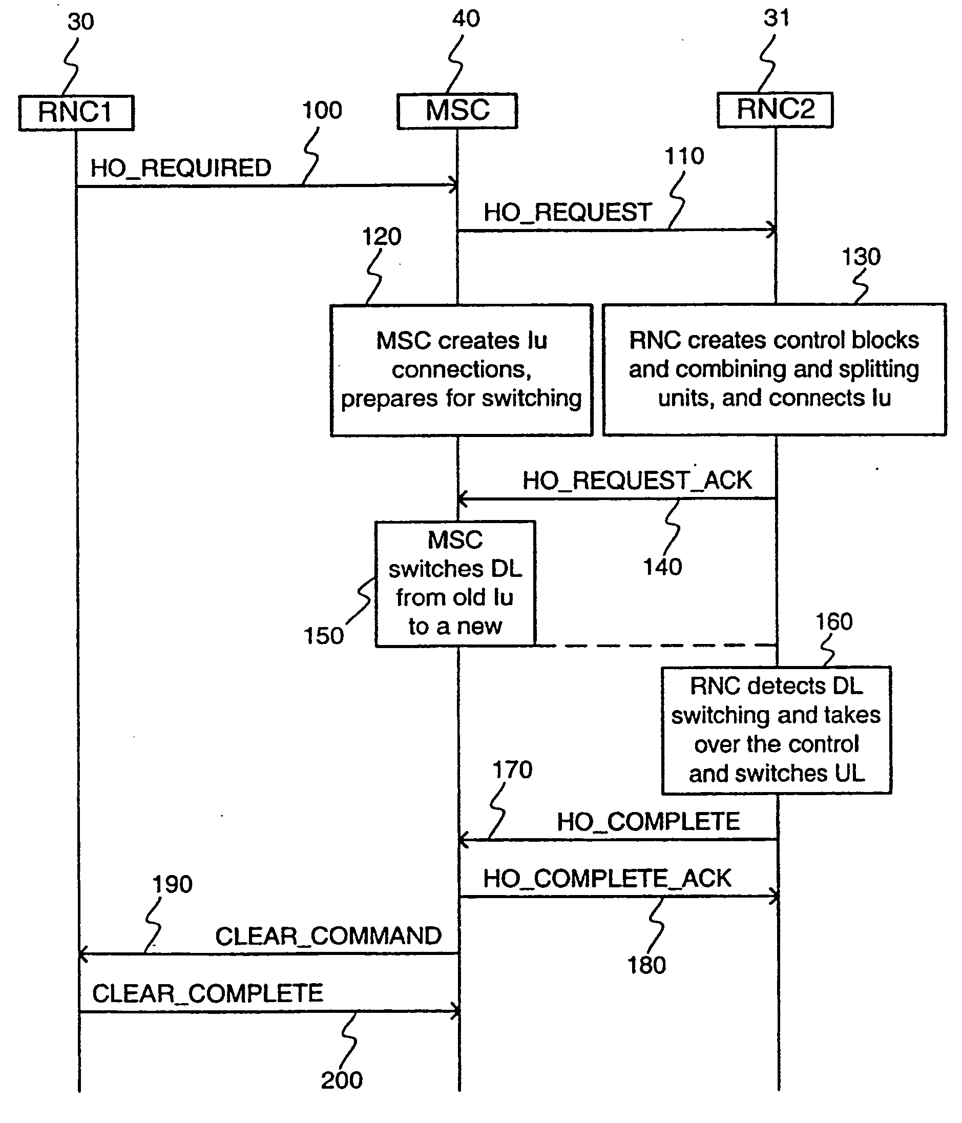
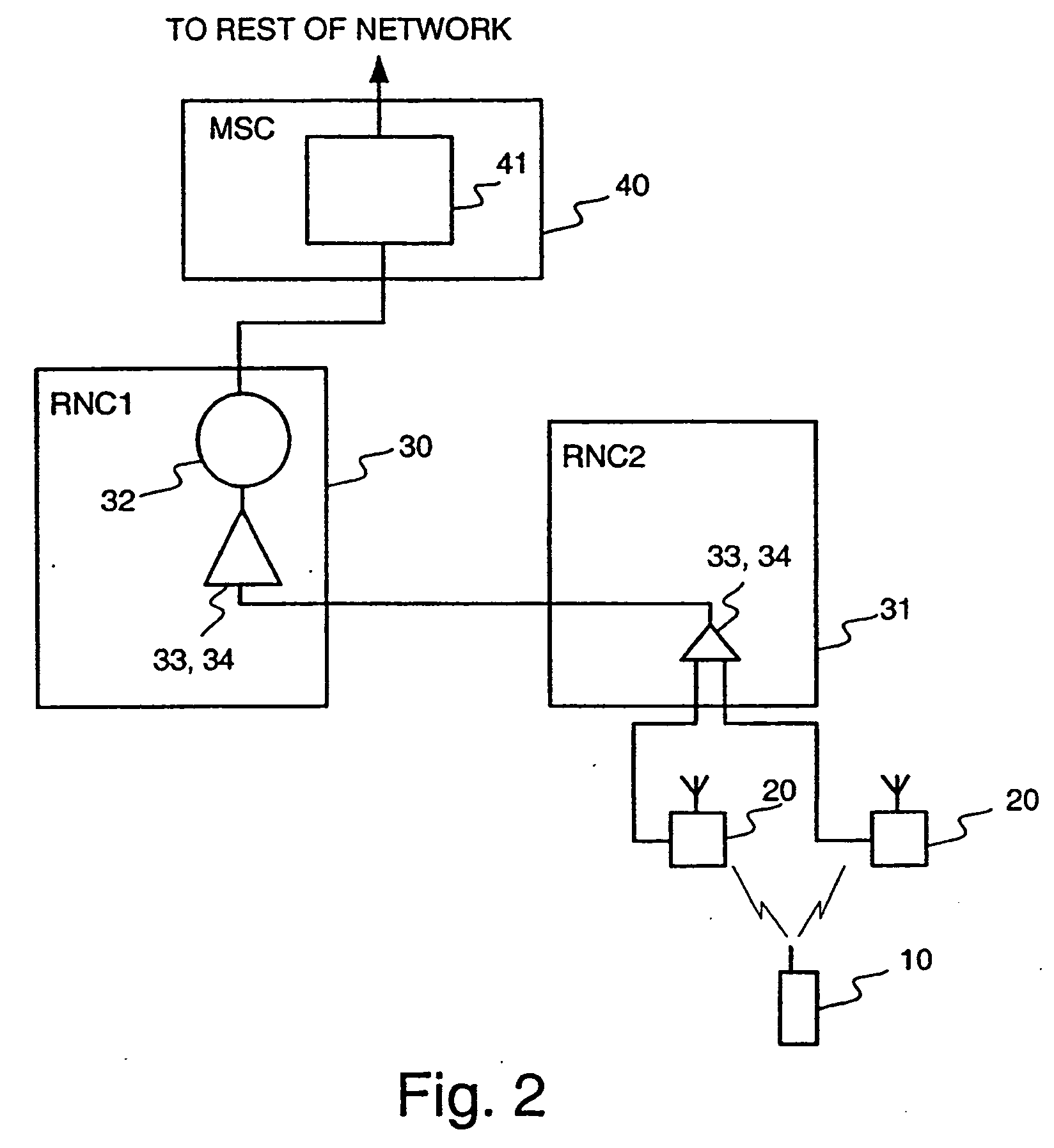
[0022] An advantageous embodiment of the invention is described in the following with reference to FIGS. 2, 3, and 4. FIG. 2 shows an initial situation, where a mobile station 10 (MS) has connections to base stations 20, which are controlled by another RNC 31 than RNC 30 that controls the connections to the mobile station. In this starting situation, RNC1 30 controls the connections to the mobile station, while the connections are routed via RNC2 31, which controls the base stations, in whose area the mobile station is currently located. This situation may arise, for example, when the mobile station initiates connections while located within a cell controlled by RNC1 30, and later moves away from that cell to another, which is controlled by RNC2 31. A mobile switching center 40 (MSC) forwards the connections from the rest of the network (not shown in FIG. 2) to the RNCs. The RNCs further comprise combining and splitting units 33, 34. Combining units 33 combine uplink signals belongi...


PUM

PropertyMeasurementUnit
lengthaaaaaaaaaa
frequencyaaaaaaaaaa
areaaaaaaaaaaa

Abstract

When a new connection is set up between a mobile station and a cellular telecommunications network, the starting frame of the new connection is selected using a simple rule so that the starting times of the interleaving periods of all the presently active connections between the mobile station and the cellular network are periodically aligned, thereby substantially simplifying the handover process. In addition, the length of the interleaving period can be set such that the periodic alignment is more frequent.

Description

[0001] The present application is a divisional application under 35 U.S.C. .sctn.121 of U.S. patent Ser. No. 09 / 674,132, which was the U.S. national stage under 35 U.S.C. .sctn.371 of International PCT Patent Application PCT / FI99 / 00268, filed on Mar. 31, 1999, which claimed priority from Finnish Patent Application No. 980736, filed on Mar. 31, 1998. Priority is claimed under 35 U.S.C. .sctn.121, 35 U.S.C. .sctn.119(a), and 35 U.S.C. .sctn.365(b) from the aforesaid Finnish Patent Application. All of the aforesaid patent applications are incorporated by reference in their entirety.[0002] 1. Field of the Invention[0003] The invention is directed to a method for optimization of transmission links in a cellular telecommunications network.[0004] 2. Description of the Related Art[0005] FIG. 1 shows an example of a situation which sometimes occurs during a hard handover, i.e., when a mobile station 10 changes the base station or base stations 20 it is presently using. Such a situation may o...

Claims


Application Information

Patent Timeline
Patent Type & Authority Applications(United States)
IPC IPC(8): H04L12/56A61K38/00C07K7/23H04L12/28H04W36/12H04W36/18
CPCA61K38/00C07K7/23H04L45/00H04W92/22H04W36/12H04W36/18H04W36/0033H04L45/85
Inventor AHMAVAARA, KALLE
Owner QUALCOMM INC
Learn More