Dual energized hydroseal

Inactive Publication Date: 2004-12-30
PROSERV OFFSHORE INC +1
View PDF24 Cites 13 Cited by
  • Summary
  • Abstract
  • Description
  • Claims
  • Application Information

AI Technical Summary

Problems solved by technology

The device does not, however, maintain this pr

Method used


Image

  • Dual energized hydroseal
  • Dual energized hydroseal
  • Dual energized hydroseal

Examples


Embodiment Construction

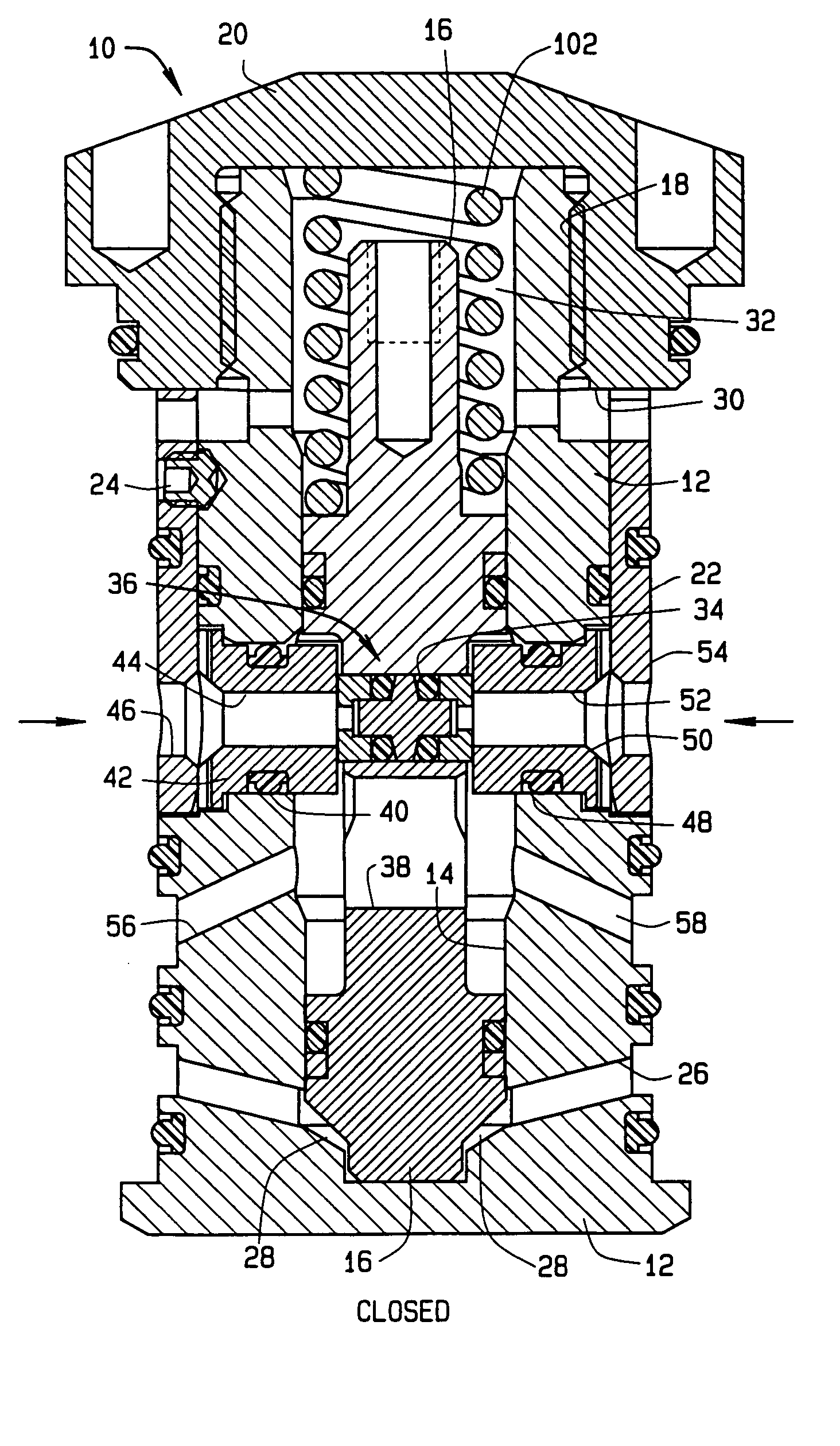
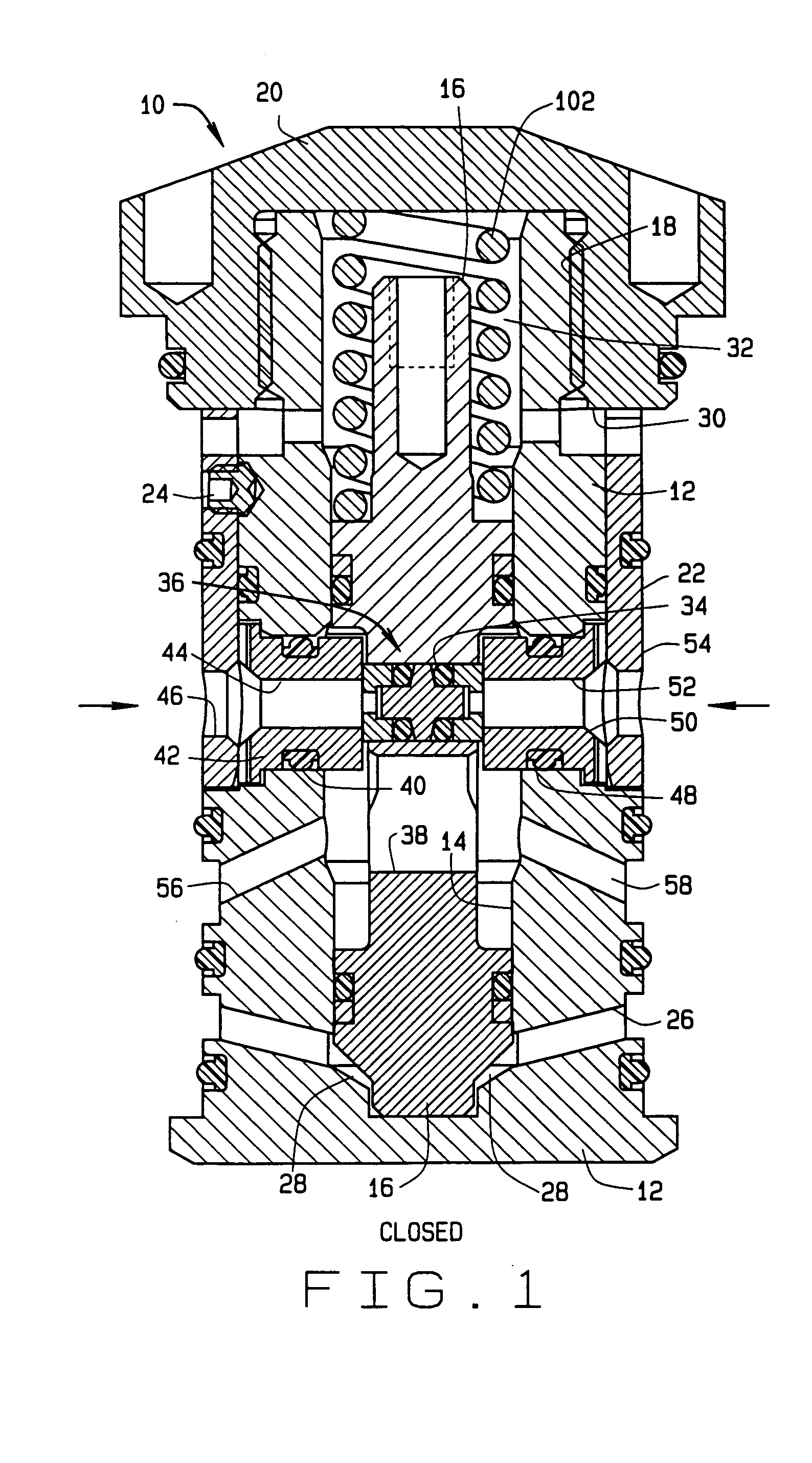
[0027] Referring to FIG. 1, the dirty fluid valve is generally identified by the numeral 10. The valve 10 is a normally closed, two position, two-way valve. The valve 10 is sometimes referred to as a "cartridge" type valve, because it is often manufactured in the configuration of FIG. 1 and it is slipped into a valve chamber in the body of a downhole tool. The downhole tool typically have--or more dirty fluid valves, to test wellbore fluids at different well depths. Each valve 10 is in fluid communication with the wellbore and a sample collection bottle to hold wellbore fluids. The valve 10 is typically rated for operational pressures of up to 30,000 psi and temperatures of up to 350.degree. F.

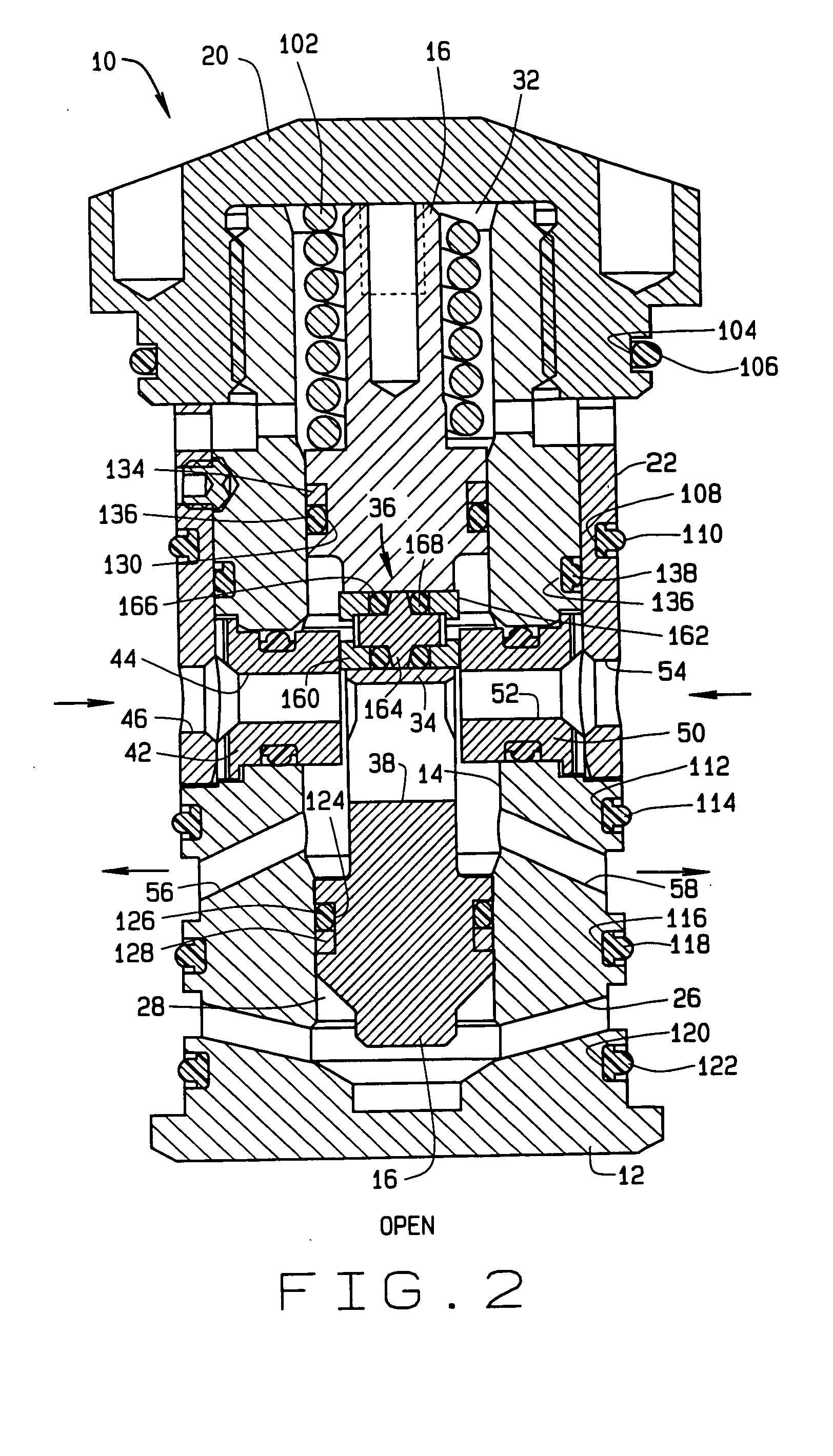
[0028] The valve 10 has a generally cylindrical body 12 which defines a longitudinal bore 14 which is sized and arranged to receive a seal carrier 16. The seal carrier moves from a normally closed position shown in FIG. 1 to an open position shown in FIG. 2.

[0029] The body 12 has threads 18 fo...


PUM


Abstract

A bi-directional seal assembly can be used in various types of cartridge valves including dirty fluid valves and a variety of other valves. The present seal assembly utilizes a seal spool, two O-rings and opposing seal cups. Back-up rings are provided to engage the O-rings to control deformation of the O-rings. The O-rings are compressed during manufacture of the seal assembly and the valve more than typically recommended by O-ring manufacturers. Because of this compression, the O-rings serve a dual function. At lower pressures, the O-rings act as a spring causing the seal cups to contact the opposing seal plates and at higher pressures they act as seals between the seal assembly and the valve.

Description

CROSS REFERENCE[0001] This is a Continuation-in-Part of application Ser. No. 10 / 017,097 filed Dec. 24, 2001 and entitled Dual Energized Hydroseal.[0002] 1. Field of the Invention[0003] The present seal assembly will function when pressured acts on it from two different directions. It is therefore sometimes referred to as a bi-directional seal or a dual energized hydroseal. The present invention can be used in a variety of different types of valves where a dual energized seal assembly is needed, as well as in cases where single-direction control is necessary.[0004] 2. Background of the Invention[0005] The dual energized hydroseal includes a seal spool, two O-rings and two opposing seal cups. This bi-directional seal assembly can be used in a dirty fluid valve and a variety of other applications where a bi-directional seal assembly is needed, as well as in cases where a single direction seal assembly is necessary. For purposes of example, the dual energized hydroseal will be described...

Claims


Application Information

Patent Timeline
IPC IPC(8): E21B49/08
CPCE21B49/081E21B49/0813
Inventor NEUGEBAUER, THOMAS W.THRASH, THOMAS B. JR.
Owner PROSERV OFFSHORE INC
Why Eureka
Try Eureka