Rubber and wire mesh ring

a technology of wire mesh and ring, which is applied in the direction of hose connection, cable termination, mechanical equipment, etc., can solve the problems of requiring additional length, requiring bulky systems, and reducing the service life of the system,

Inactive Publication Date: 2005-03-08
MORVANT JOHN D
View PDF12 Cites 12 Cited by
  • Summary
  • Abstract
  • Description
  • Claims
  • Application Information

AI Technical Summary

Benefits of technology

A wire encapsulated back-up ring is disclosed having a co-efficient of thermal expansion while the ring is under pressure which is less than or equal to the surrounding gland metal. The upper surface of the back-up ring is concave to allow pressure to energize the back-up ring. The outer and inner surfaces normally remain in contact with adjacent portions of the gland and maintain an anti-extrusion barrier for a sealing ring. The anti-extrusion element also has a lower surface adapted to mate with or be a support member behind the anti-extrusion element. If the back-up ring is not also the support member, the support member surface may have a shape as required to hold the element or elements in place. The body of the element includes two parts. The first part is a wire mesh, used for reinforcement. Such apart would typically be formed in a vee shape, but may deviate to conform to the support member. The second part is a coating of sealing material which would encapsulate the wire mesh shape. The coating may vary in thickness around the wire mesh shape. The coating thickness would depend upon the strength requirement of the seal.

Problems solved by technology

However, under pressure, such seals may be eroded or destroyed and require back-up rings to prevent extrusion of the seal rings.
Such systems, however, are bulky and require additional length.
At times they require structures with different materials as back-up rings and require a modules of materials at escalating values, which must be maintained even at high temperatures, which is not possible.

Method used


Image

  • Rubber and wire mesh ring
  • Rubber and wire mesh ring
  • Rubber and wire mesh ring

Examples


Embodiment Construction

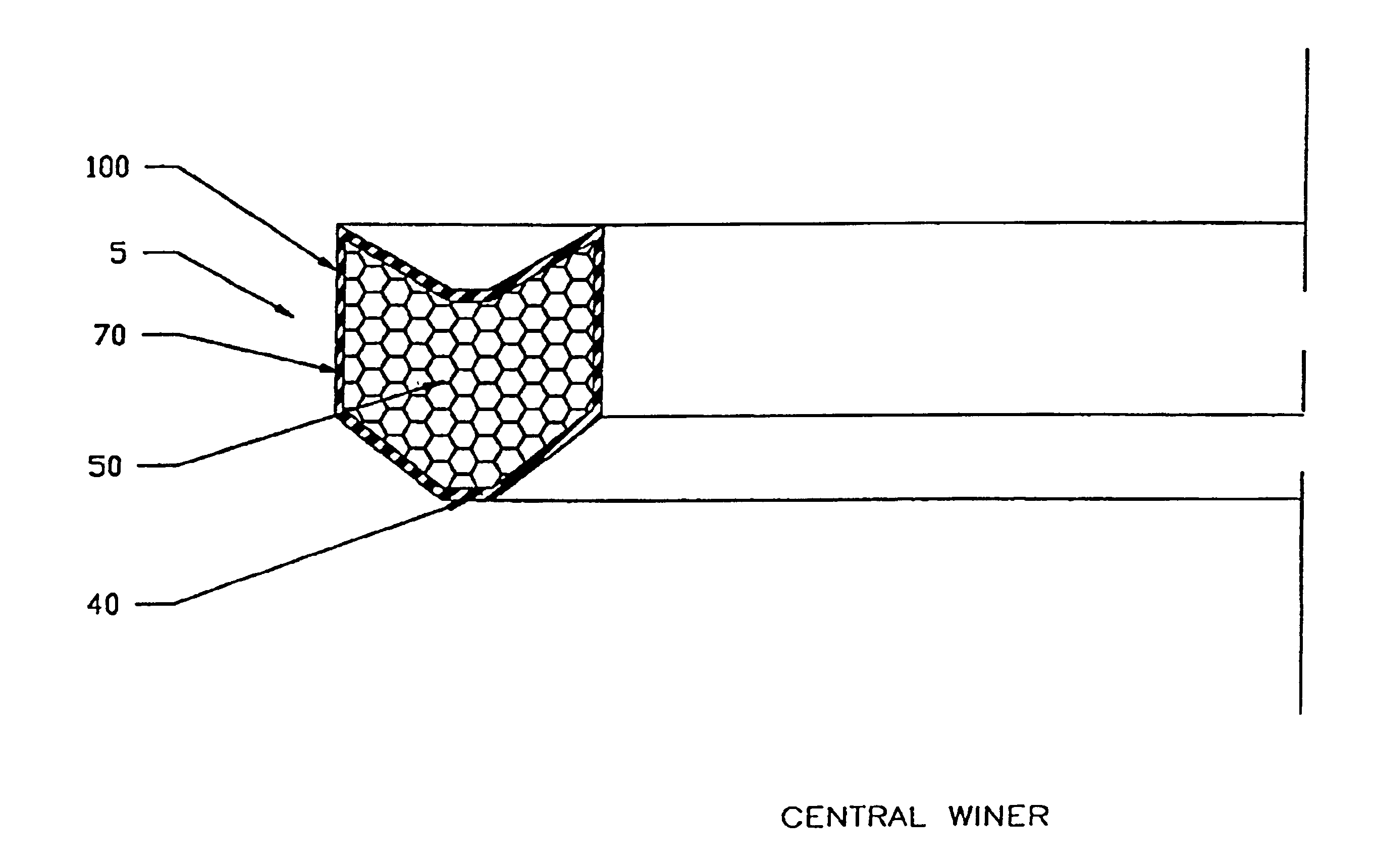
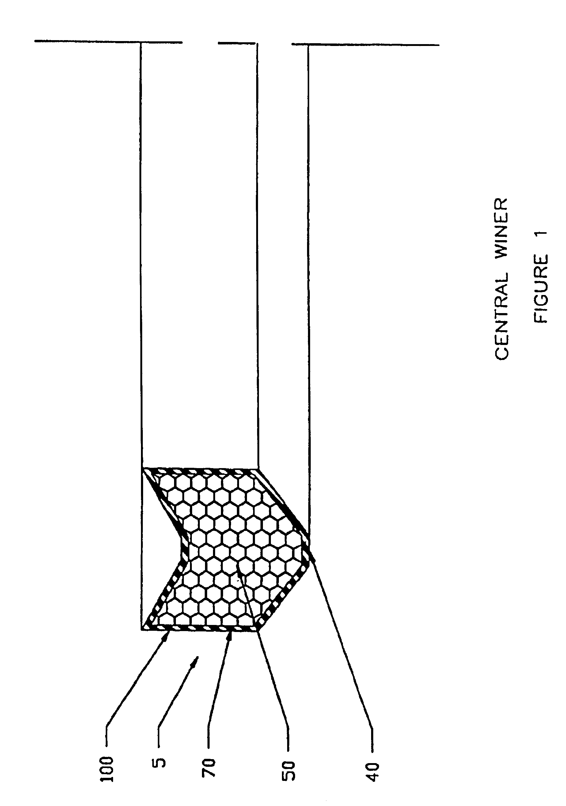
As seen in FIG. 1, the back-up ring 5 of the present invention is shown having wire mesh vee shape 50 with an outer coating 100 of sealing material 70. This permits back-up ring 5 with the wire mesh 50 to have increased physical strength. The back-up ring 5 retains nearly all physical strength at high temperatures and thermally expands negligibly compared to the typical vee ring. The materials are such that a co-efficient of thermal expansion while the back-up ring 5 is under pressure is less than or equal to the surrounding gland metal.

Referring to FIG. 7, the surfaces of back-up ring 5 include an upper surface 10, which has a modified vee shape with a horizontal portion 11 and angled sides 12, a vertical inner surface 20 and a vertical outer surface 30. Surfaces 20, 30 are preferably symmetrical. Surface 10 is concave to allow pressure to energize surfaces 20, 30 of back-up ring 5. Surfaces 20, 30 remain in contact with their adjacent conduits 120, 130, respectively, and maintain ...


PUM


Abstract

A back-up ring is disclosed wherein the ring is a knitted mesh section substantially surrounded by an outer coating covering substantially all of the knitted wire mesh section, the coating having contact with the outer and inner surface of an annulus.

Description

FIELD OF THE INVENTIONThe present invention relates to anti-extrusion rings and, more particularly, to wire encapsulated extrusion rings.BACKGROUND OF THE INVENTIONSeals have been used to isolate fluids at various pressures and temperatures. Such seals have existed for use in packing rings, seal rings, piston rings and gland structures in industrial equipment, such as cylinders, pumps, hydraulics and valves, and in oil field equipment, such as down hole tools and surface equipment, requiring seals, for example, against high pressure and low pressure liquids and gases. Typically, these seals are annular seals.However, under pressure, such seals may be eroded or destroyed and require back-up rings to prevent extrusion of the seal rings. See, for example, U.S. Pat. No. 4,234,197, issued Nov. 18, 1982, Amancharla, et al, entitled Conduit Sealing System. Such systems, however, are bulky and require additional length. At times they require structures with different materials as back-up ri...

Claims


Application Information

Patent Timeline
Patent Type & Authority Patents(United States)
IPC IPC(8): F16J15/18F16J15/16F16J15/20F16J15/32
CPCF16J15/166F16J15/3232F16J15/20
Inventor MORVANT, JOHN D.
Owner MORVANT JOHN D
Why Eureka
Try Eureka