
Welding tool and welding method

A welding tooling and tooling technology, applied in the field of welding tooling and welding, can solve problems such as low efficiency of welding metal shells

Active Publication Date: 2020-04-21
HUBEI SANJIANG AEROSPACE GRP HONGYANG ELECTROMECHANICAL
View PDF8 Cites 12 Cited by
  • Summary
  • Abstract
  • Description
  • Claims
  • Application Information

AI Technical Summary

Problems solved by technology

[0004] The embodiment of the present application solves the technical problem of low efficiency of the existing welding metal shell by providing a welding tool and a welding method

Method used


Image

  • Welding tool and welding method
  • Welding tool and welding method
  • Welding tool and welding method

Examples


Embodiment 1

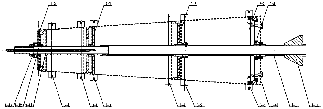
[0044] Such as figure 1 As shown, this embodiment provides a welding tool for welding a metal shell, the metal shell includes a plurality of end frames and a plurality of skins;

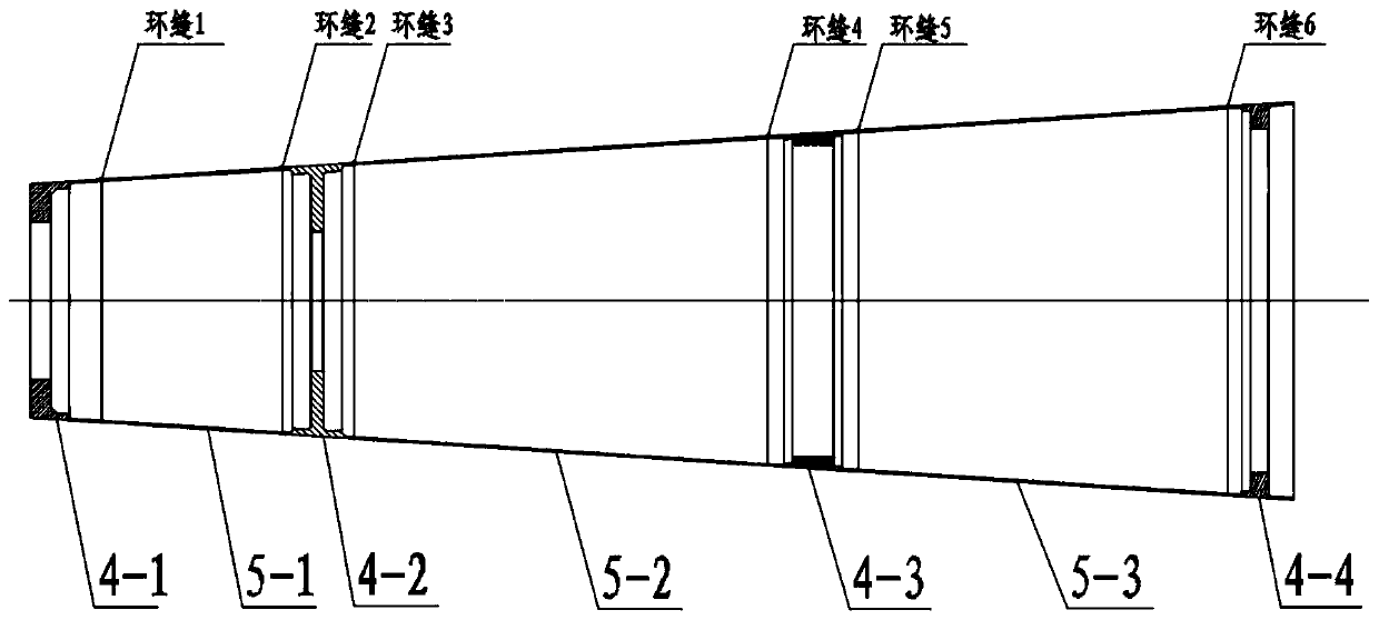
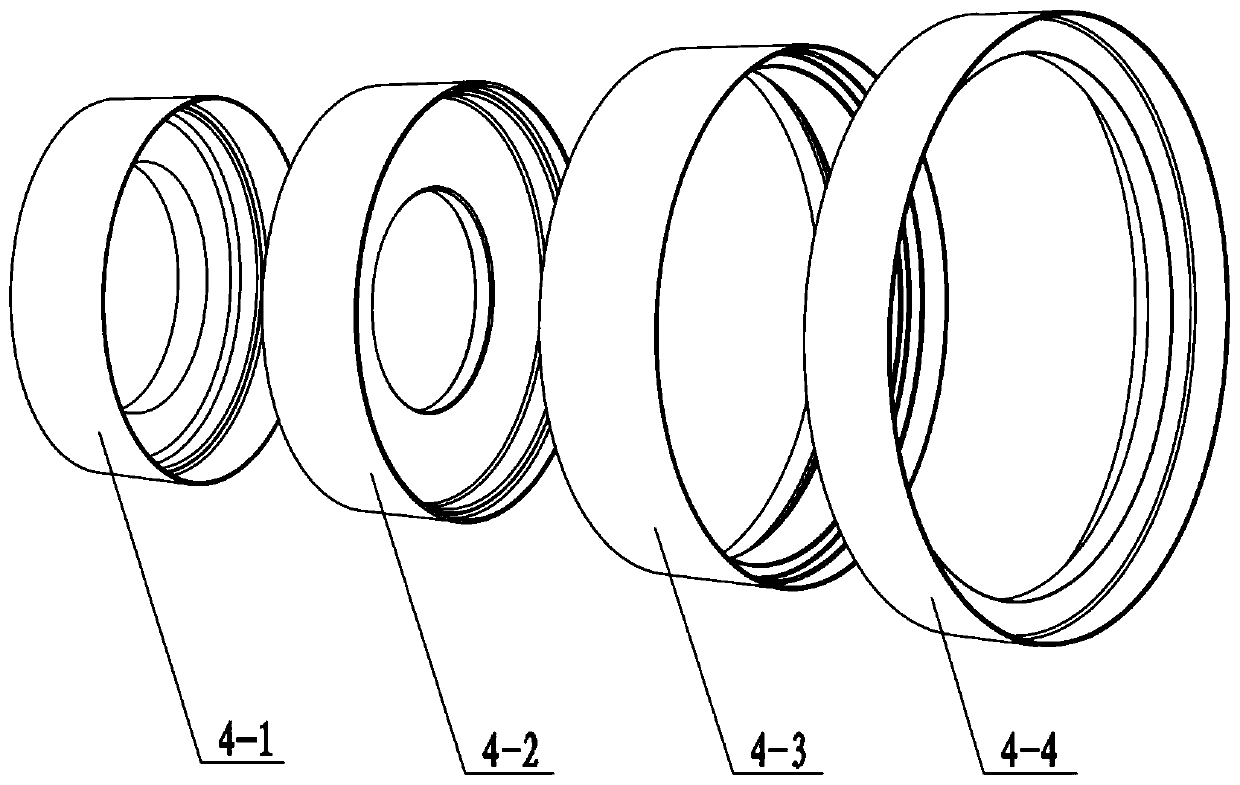
[0045] It should be noted that the metal shell in this embodiment may be a metal shell such as aluminum, iron, copper, or an alloy shell, which is generally welded by multiple end frames and multiple skins. As a typical aluminum alloy shell, see image 3 and Figure 4 , composed of 4 types of end frames + 3 types of skins, a total of 7 parts assembled and welded, including: the first end frame 4-1, the second end frame 4-2, the third end frame 4-3 and the fourth end frame 4-4, and a first skin 5-1, a second skin 5-2 and a third skin 5-3. see figure 2 , involving a total of 6 circular welds (circular seam 1, circular seam 2, circular seam 3, circular seam 4, circular seam 5, circular seam 6, among which, circular seam 1 has the smallest diameter and circular seam 6 has the largest diameter) , th...

Embodiment 2

[0069] Based on the tooling of Embodiment 1, this embodiment provides a welding method for welding a metal shell, the metal shell includes a plurality of end frames and a plurality of skins,

[0070] It should be noted that in practical applications, the outer surface of the aluminum alloy shell as described in Example 1 will be covered with a composite material heat-proof layer, so the requirements for the shape and position tolerance of the shell are relatively strict, and the front and rear end frames of the shell will be It is connected with other compartments, so the requirements for the relative position of the front and rear end frames are relatively strict. These all put forward higher requirements for the quality control of the shell. The existing three-time welding method has a large cumulative error and cannot meet the quality requirements. Require.

[0071] For this, see Figure 8 , the welding method of this implementation, including:

[0072] S101. On the tooli...


PUM

PropertyMeasurementUnit
lengthaaaaaaaaaa
heightaaaaaaaaaa
Circularityaaaaaaaaaa

Abstract

The invention discloses a welding tool which comprises a positioning assembly, an inner supporting assembly and an outer restraining assembly. The positioning assembly comprises a positioning shaft and a plurality of positioning discs coaxially fixed on the positioning shaft, and a plurality of positioning discs are used for fixing a plurality of end frames; the outer restraining assembly comprises a plurality of outer clamping rings which are used for clamping the joint part of the end frames and the skin, and spot welding grooves used for exposing the joint part are arranged in the outer clamping rings; the inner supporting assembly comprises an inner supporting disc and an inner supporting ring. The inner supporting ring is detachable and is used for internally supporting a seam part atthe rearmost end of the metal shell; and the inner supporting disc is used for supporting the joint part in the metal shell. The tool can be used for continuously welding the seam part without usingmultiple sets of welding tools for multiple times of welding in the prior art, the welded metal shell is convenient to disassemble and assemble through the detachable outer clamping ring and the innersupporting ring and thus the welding efficiency is remarkably improved.

Description

technical field [0001] The invention relates to the technical field of metal welding, in particular to a welding tool and a welding method. Background technique [0002] With the development of spacecraft equipment, model development presents the development characteristics of high-efficiency, high-quality and low-cost manufacturing, and the equipment iteration cycle is greatly accelerated. The cabin shell of the model mainly adopts the structural form of aluminum alloy shell + heat-proof layer , to provide filling space, load bearing and thermal protection for internal installation parts. In practice, the aluminum alloy shell is generally assembled and welded by 4 types of end frames + 3 types of skins, a total of 7 parts. There are 6 circumferential welds in total, and the length of the welds is 12.9m. The number of welds and the length of the welds are equal It is the best of its kind. The product requires welds to meet the Class I standard in QJ2698A-2011. As the numb...

Claims


Application Information

Patent Timeline
Patent Type & Authority Applications(China)
IPC IPC(8): B23K37/053B23K31/02
CPCB23K37/053B23K31/02
Inventor 丁永宏王维新张军贺春影肖丽钱春雨
Owner HUBEI SANJIANG AEROSPACE GRP HONGYANG ELECTROMECHANICAL
Learn More