Automobile beam

a technology for motor vehicles and beams, applied in the field of motor vehicle beams, can solve the problems of increasing the cost of parts, difficult to adapt to particular geometrical configurations, and relatively heavy parts

Active Publication Date: 2004-12-30
CO PLASTIC OMNIUM
View PDF18 Cites 46 Cited by
  • Summary
  • Abstract
  • Description
  • Claims
  • Application Information

AI Technical Summary

Benefits of technology

0009] An object of the invention is to propose a solution making it possible to take advantage of the capacity of beams made of plastics material to adapt easily to specific shapes, and of the rigidity procured by one or more metal strength members, without suffering from the drawbacks of such metal members.

Problems solved by technology

However, such parts suffer from the drawback of being relatively heavy.
In addition, they are not easy to adapt to particular geometrical configurations that might be required by the vehicle, sometimes requiring additional parts that can be referred to as "absorbers".
However, because of the low rigidity inherent to the materials used, such parts made of plastics material must have complex structures, in particular ribs, and the material used must be mixed with reinforcing fibers which increase its cost and make manufacturing the parts more complex, thereby tending to diminish the advantages procured by use of plastics material, without completely eliminating them.

Method used


Image

  • Automobile beam
  • Automobile beam
  • Automobile beam

Examples


Embodiment Construction

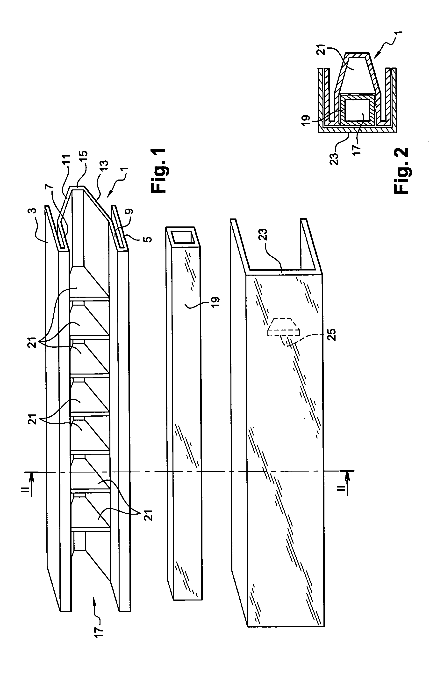
[0039] In the example described, the beam has a shell 1 of W-shaped cross section made of polypropylene filled with glass fibers that are long (longer than 1 mm). The shell is obtained by injection molding under usual conditions.

[0040] Because of its W-shaped cross-section, the shell has, going from its outside inwards, two mutually parallel outer longitudinal edges, namely a top outer edge 3 and a bottom outer edge 5, connected respectively to a top inner edge 7 and to a bottom inner edge 9, which inner edges are parallel to the outer edges, and are extended by respective ones of two converging walls 11 and 13 interconnected by an end wall 15.

[0041] The inner longitudinal edges 7 and 9, the converging walls 11 and 13, and the end wall 15 constitute an open U-shaped portion of the shell cross-section, and they define an elongate recess 17 for receiving a strength member in the form of a cross-member, constituted in this example by a metal tube 19 of rectangular cross-section.

[0042] ...


PUM


Abstract

The invention relates to a motor vehicle beam shell designed to be placed behind a bumper skin, said shell being provided with a recess for receiving a strength member inside it, the strength member being, for example, a strength member made of metal, in particular of aluminum, or a strength member made of a composite material incorporating a metal. The beam is provided with shell cladding which interfits with the shell, thereby forming a hollow body defining a recess for receiving the strength member.

Description

[0001] The present invention relates to a motor vehicle beam shell and to a motor vehicle beam.[0002] It is known that motor vehicle bumpers have cross-beams whose function is to absorb a large portion of the energy from impacts.[0003] A test in wide use, in particular in the United States, for verifying the strength of a bumper is known as the "pole test". Such a test consists in subjecting the rear of the vehicle to an impact on its middle axis at a speed of 8 kilometers per hour (km / h) against a fixed pole that is 7 inches (about 178 millimeters (mm)) in diameter. The test is considered to be satisfactory if the cost of repairing the vehicle after such a test is lower than a certain threshold.[0004] In order to limit the repair costs resulting from such an impact, it is essential to minimize the damage to the rear of the vehicle, and thus to limit the extent to which the pole penetrates into the rear face of the vehicle during the impact, e.g. by putting into place a cross-member...

Claims


Application Information

Patent Timeline
Patent Type & Authority Applications(United States)
IPC IPC(8): B60R19/18B60R19/24
CPCB60R19/18B60R19/24B60R19/48B60R2019/182B60R2019/1853B60R2019/1866
Inventor ROUSSEL, THIERRYMALTESTE, STEPHANEPIERROT, FREDERIC
Owner CO PLASTIC OMNIUM
Why Eureka
Try Eureka