Power-on reset circuit with supply voltage and temperature immunity, ultra-low DC leakage current, and fast power crash reaction

a power-on reset and supply voltage technology, applied in pulse generators, instruments, pulse techniques, etc., can solve the problems of insufficient operation of other components, supply signal reduced to a very low level, and difficulty in fabricating an integrated circuit with different threshold voltages,

Inactive Publication Date: 2004-12-30
MACRONIX INT CO LTD
View PDF8 Cites 21 Cited by
  • Summary
  • Abstract
  • Description
  • Claims
  • Application Information

AI Technical Summary

Problems solved by technology

When in a low power mode, the supply signal is reduced to a very low level, sufficient to allow some devices to operate but insufficient to allow other components to operate.

Method used


Image

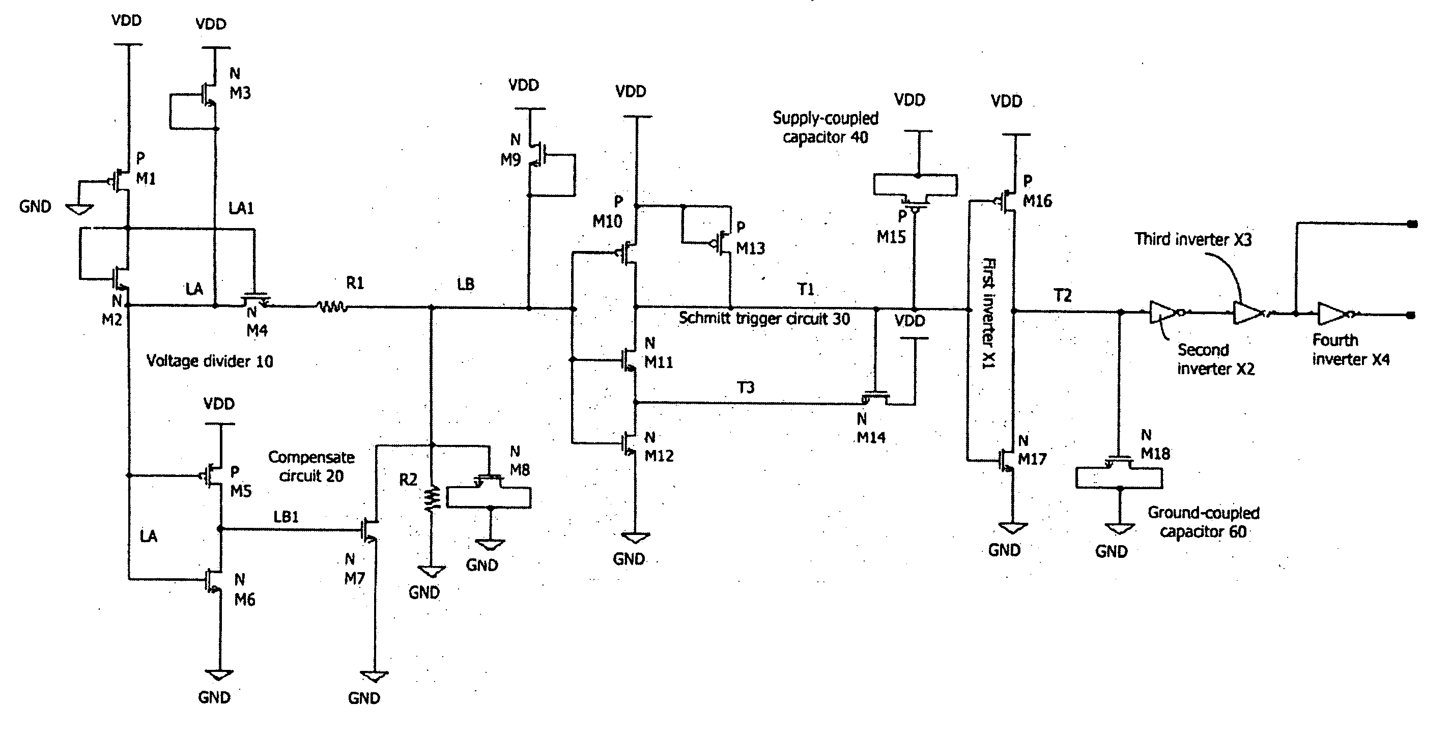
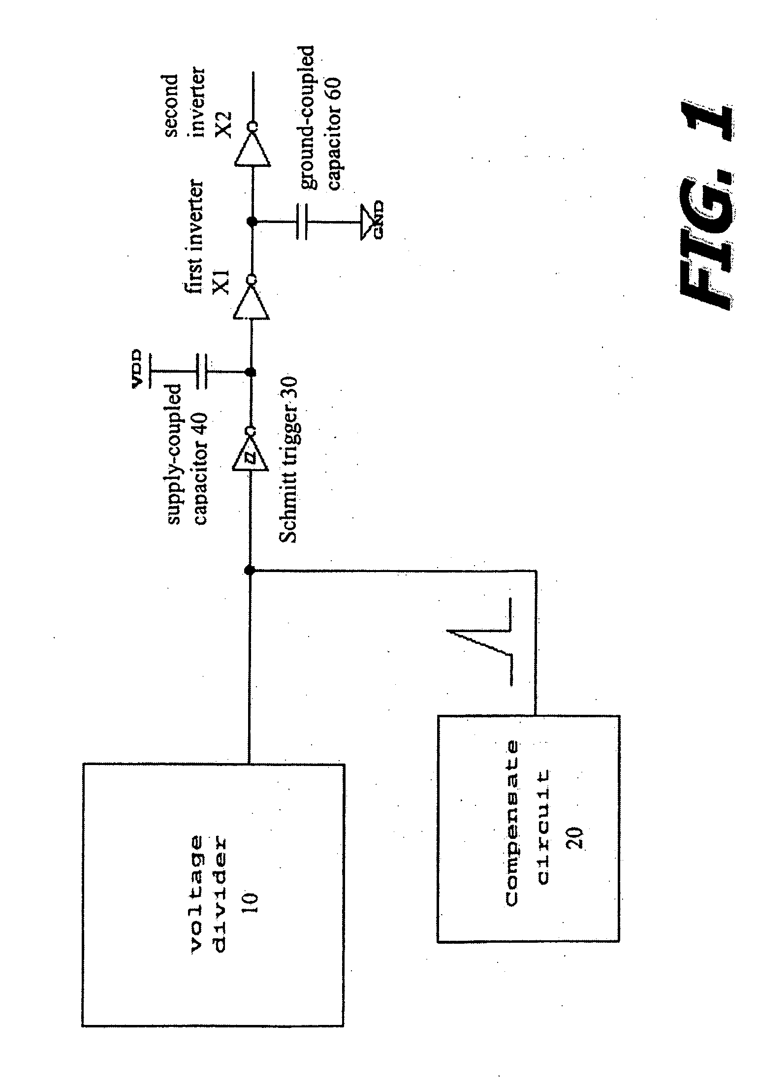
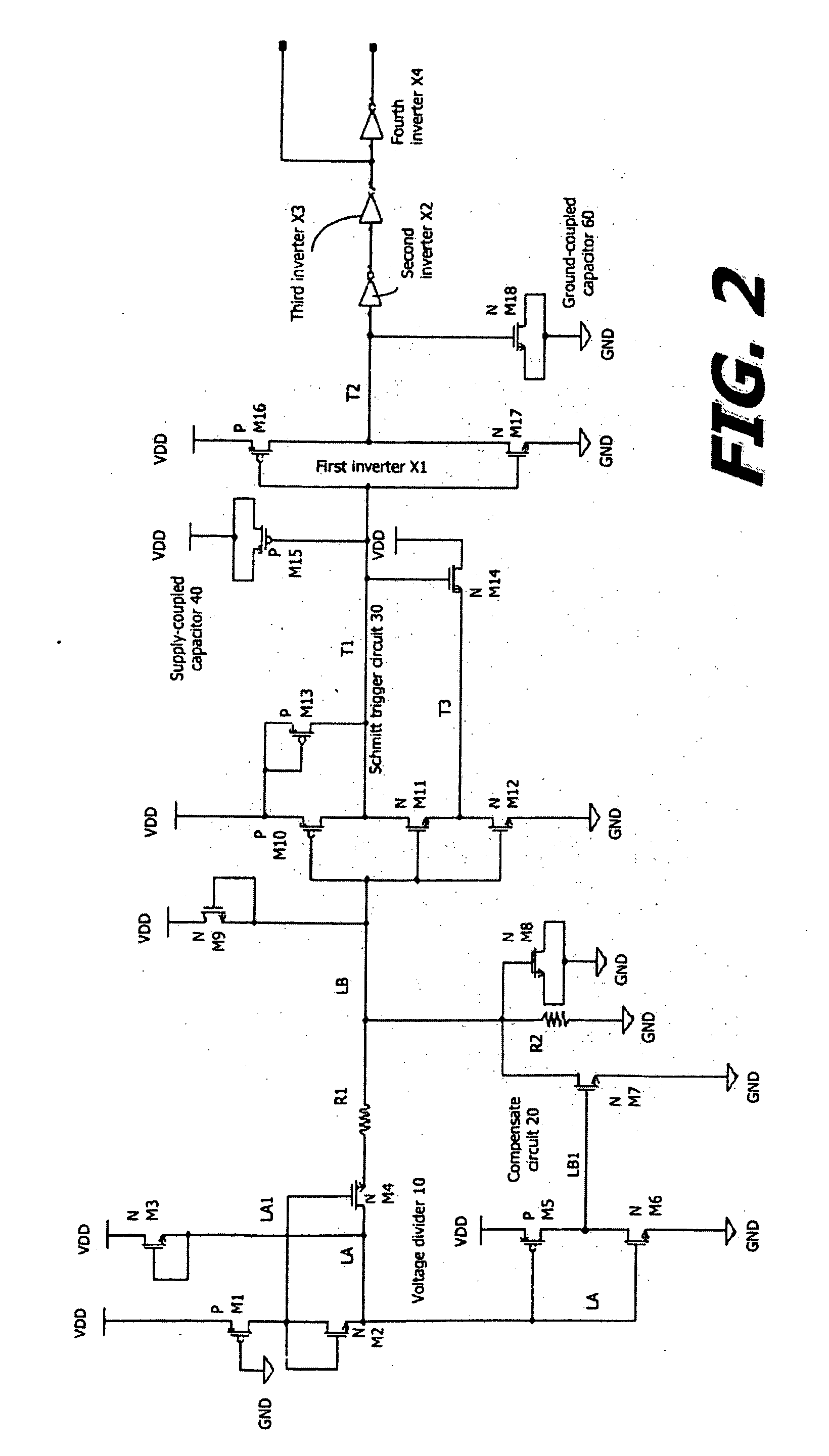
  • Power-on reset circuit with supply voltage and temperature immunity, ultra-low DC leakage current, and fast power crash reaction
  • Power-on reset circuit with supply voltage and temperature immunity, ultra-low DC leakage current, and fast power crash reaction
  • Power-on reset circuit with supply voltage and temperature immunity, ultra-low DC leakage current, and fast power crash reaction

Examples


Embodiment Construction

[0024] Reference will now be made in detail to the presently preferred embodiments of the invention, examples of which are illustrated in the accompanying drawings. Wherever possible, the same or similar reference numbers are used in the drawings and the description to refer to the same or like parts. It should be noted that the drawings are in simplified form and are not to precise scale. In reference to the disclosure herein, for purposes of convenience and clarity only, directional terms, such as, top, bottom, left, right, up, down, over, above, below, beneath, rear, and front, are used with respect to the accompanying drawings. Such directional terms should not be construed to limit the scope of the invention in any manner.

[0025] Although the disclosure herein refers to certain illustrated embodiments, it is to be understood that these embodiments are presented by way of example and not by way of limitation. The intent of the following detailed description, although discussing e...


PUM


Abstract

A power-on reset circuit includes a Schmitt trigger circuit, a voltage divider, and a compensate circuit. The Schmitt trigger circuit includes a plurality of MOS devices of a uniform threshold voltage (V.sub.t) for determining a power reset trigger level. The voltage divider is coupled to an input of the Schmitt trigger circuit for tracking the supply signal. The compensate circuit is operative to generate a small reset pulse to compensate for temperature and the supply signal variation effect.

Description

[0001] 1. Field of the Invention[0002] The present invention relates generally to power supply circuitry and, more particularly, to power-on resets for power supply circuitry.[0003] 2. Description of Related Art[0004] Traditionally, an electronic device has required a power supply that provides a relatively constant voltage to the electronic device. In such devices, when power is initially applied to the electronic device, a supply signal increases non-instantaneously from a ground potential to an operational level. When the supply signal exceeds a threshold, a "power-on reset" signal indicates to the various components that sufficient voltage is available on the supply signal. The various components of the electronic device may then initialize to a predetermined state in response to the power-on reset signal. In many electronic devices, each time the power-on reset signal is asserted, the electronic device enters the same predetermined state.[0005] Many electronic devices also have...

Claims


Application Information

Patent Timeline
IPC IPC(8): H03K3/3565H03K17/14H03K17/22H03L7/00
CPCH03K3/3565H03K17/145H03K17/223G11C5/148G11C7/04G11C7/20
Inventor TSENG, CHIEN-CHUNGHSU, CHIH-NENG
Owner MACRONIX INT CO LTD
Why Eureka
Try Eureka