
Signal processing unit for correcting shading of image signal, and electronic camera

Inactive Publication Date: 2004-12-30
NIKON CORP
View PDF2 Cites 20 Cited by
  • Summary
  • Abstract
  • Description
  • Claims
  • Application Information

AI Technical Summary

Benefits of technology

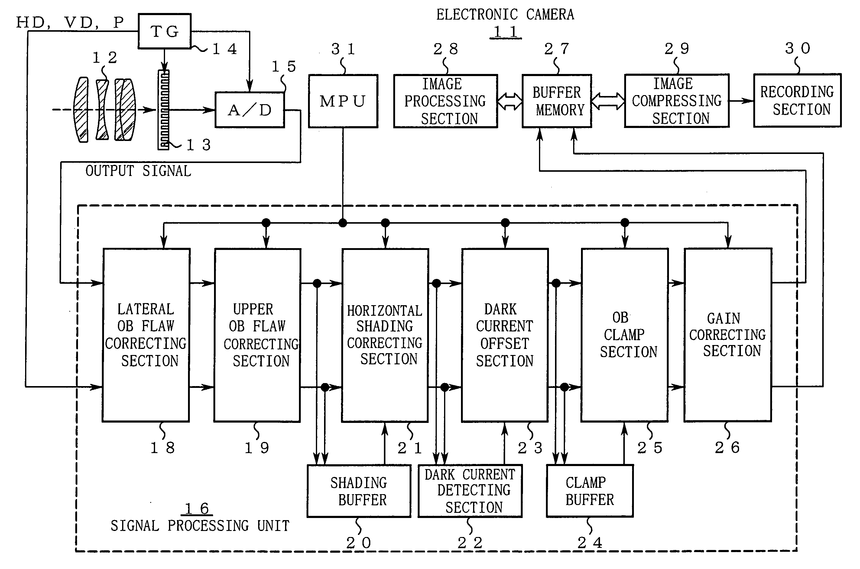
[0018] The signal processing unit includes an OB shading correcting section and a dark current offset section. More specifically, the OB shading correcting section obtains shading based on an output signal from the optical black area (hereinafter referred to as an "OB signal") to subtract the shading from the OB signal, thereby obtaining respective shading-corrected OB signals. On the other hand, the dark current offset section averages the shading-corrected OB signals to obtain a dark current level of the image pickup part so as to remove dark current offset generated in an output signal from the effective pixel area based on the dark current level.
[0019] The inventor of the present invention has found the other cause for the generation of noises due to shading correction. More specifically, as exposure time of the image pickup part becomes longer, the amount of a dark current contained in the output signal is more increased. The increased amount of the dark current causes a black level of an image to be needlessly increased, thereby lowering the contrast in the black area.
[0021] Therefore, in the unit according to the present invention, shading correction is performed on the OB outputs to obtain the amount of a dark current based on the shading-corrected OB outputs. In this case, occurrence of a phenomenon that the shading in a low band is doubly subtracted from the output signals is reduced. As a result, a noise due to black compression in a dark area is clearly reduced.

Problems solved by technology

If the OB clamp is carried out using the lateral OB signal having the elevated signal level, no margin is left for a black level, thereby causing a noise due to black compression in a dark area.
The increased amount of the dark current causes a black level of an image to be needlessly increased, thereby lowering the contrast in the black area.
At this time, if the amount of shading contained in the OB output is large, an error is occurred in estimation of the amount of the dark current.
As a result, contrary to the intended purpose of the signal processing, a dark area of the image is compressed to generate a noise due to black compression.

Method used


Image

  • Signal processing unit for correcting shading of image signal, and electronic camera
  • Signal processing unit for correcting shading of image signal, and electronic camera
  • Signal processing unit for correcting shading of image signal, and electronic camera

Examples


Embodiment Construction

[0071] FIGS. 5[A] and [B] are diagrams illustrating signal processing in a conventional example.

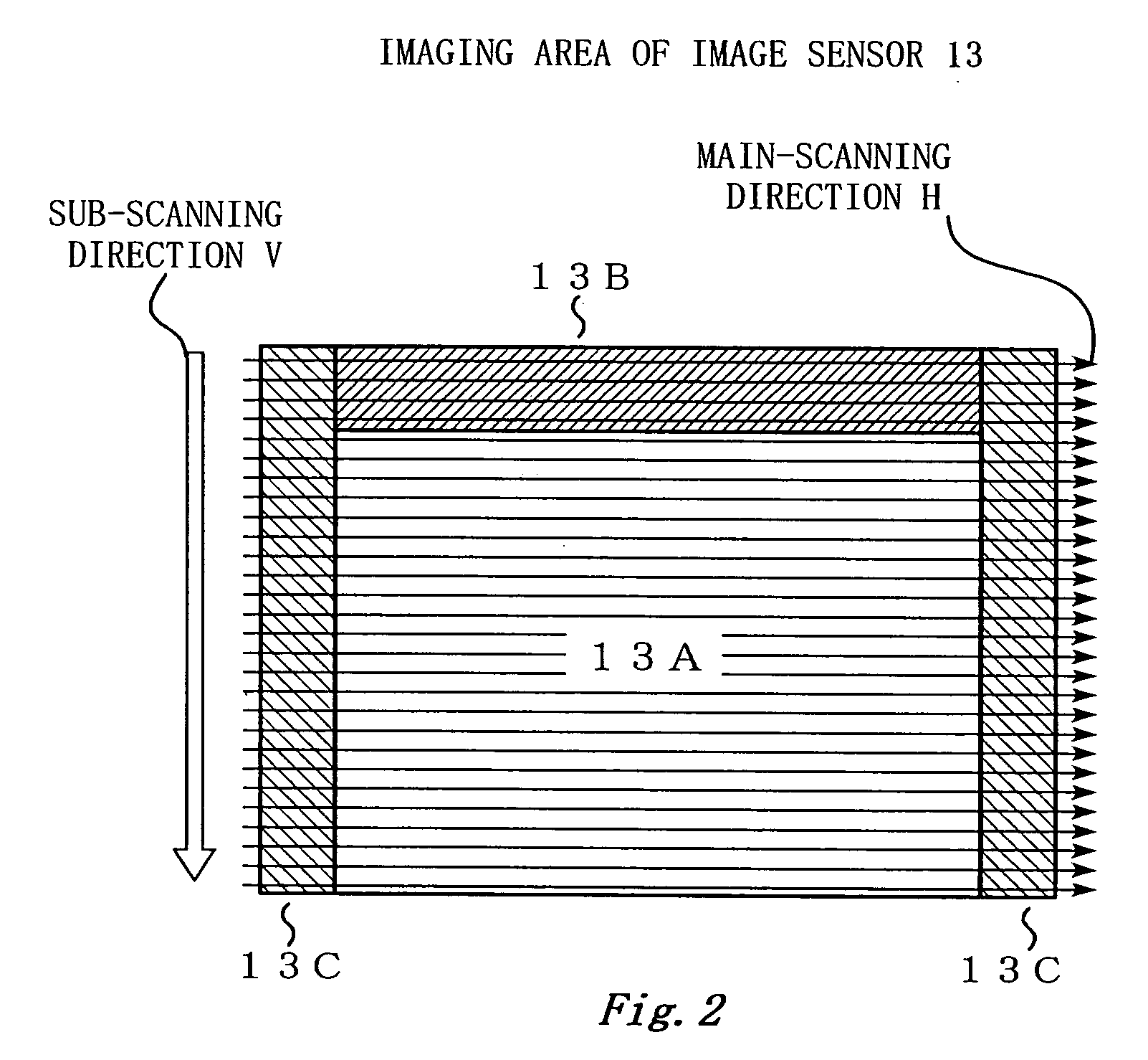
[0072] Lateral OB signals shown in FIG. 5[A] have not been subjected to shading correction and dark current offset correction yet. In the conventional example, OB clamp is executed using the lateral OB signals not having been corrected as a standard.

[0073] Normally, the amount of shading in the lateral OB signals is relatively large, depending on a variation of each image sensor 13. FIG. 5[A] shows a case where the lateral OB signals become larger than the output signals from the effective pixel area (in particular, a dark area) due to the amount of shading. In this case, as shown in FIG. 5[B], a noise due to black compression is generated in a dark area after OB clamp.

[0074] On the other hand, no noise due to black compression is generated after OB clamp as shown in FIG. 4[D] in the above-described embodiment, even when the output signals are under the same condition as those of the conv...


PUM


Abstract

A signal processing unit or an electronic camera according to the present invention performs signal processing on an output signal from an image pickup part in the order of horizontal shading correction and OB clamp. In the horizontal shading correction, shading correction is also pre-performed on a lateral OB signal serving as a standard of the OB clamp. The OB clamp is performed using the shading-corrected lateral OB signal as a standard, whereby a noise generated due to shading correction can be effectively reduced.

Description

[0001] The disclosure of the following priority application is herein incorporated by reference: Japanese Patent Application No. 2003-146046, filed May 23, 2003.[0002] 1. Field of the Invention[0003] The present invention relates to a signal processing method of an image signal. In particular, the present invention relates to a signal processing method of correcting an output signal from an effective pixel area by using an output signal from an optical black area (hereinafter referred to as an "OB signal") of an image pickup part.[0004] 2. Description of the Related Art[0005] An image device described in Japanese Unexamined Patent Application Publication No. 2002-335454 (hereinafter referred to as "Patent Document 1") is conventionally known. The image device described in the Patent Document 1 (in particular, FIG. 1 and the paragraphs [0038] and [0084]) is provided with a structure such as an OB clamp section and a shading correcting section.[0006] The OB clamp section uses an OB si...

Claims


Application Information

Patent Timeline
IPC IPC(8): H04N1/407H04N5/228H04N5/335H04N5/357H04N5/361H04N5/363H04N5/378H04N101/00
CPCH04N5/361H04N25/63
Inventor TSUDA, YUTAKA
Owner NIKON CORP
Learn More