Sludge dryer

a technology of sludge dryer and sludge, which is applied in the direction of drying machines with progressive movements, lighting and heating apparatus, furnaces, etc., can solve the problems of reducing or destroying the fertile quality of the end product, and achieve the effect of preventing the loss of partial vacuum

Inactive Publication Date: 2005-01-06
RAGNARSSON ANDERS T
View PDF21 Cites 47 Cited by
  • Summary
  • Abstract
  • Description
  • Claims
  • Application Information

AI Technical Summary

Benefits of technology

[0019] c) substantially preventing loss of the partial vacuum from the second stage at a location between the first and second stages;

Problems solved by technology

In addition the high temperatures involved tend to reduce or destroy the fertile quality of the end product.

Method used


Image

  • Sludge dryer
  • Sludge dryer
  • Sludge dryer

Examples


Embodiment Construction

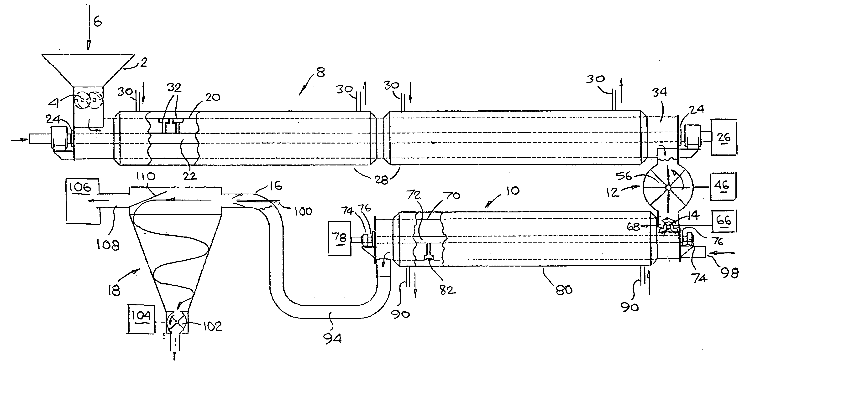
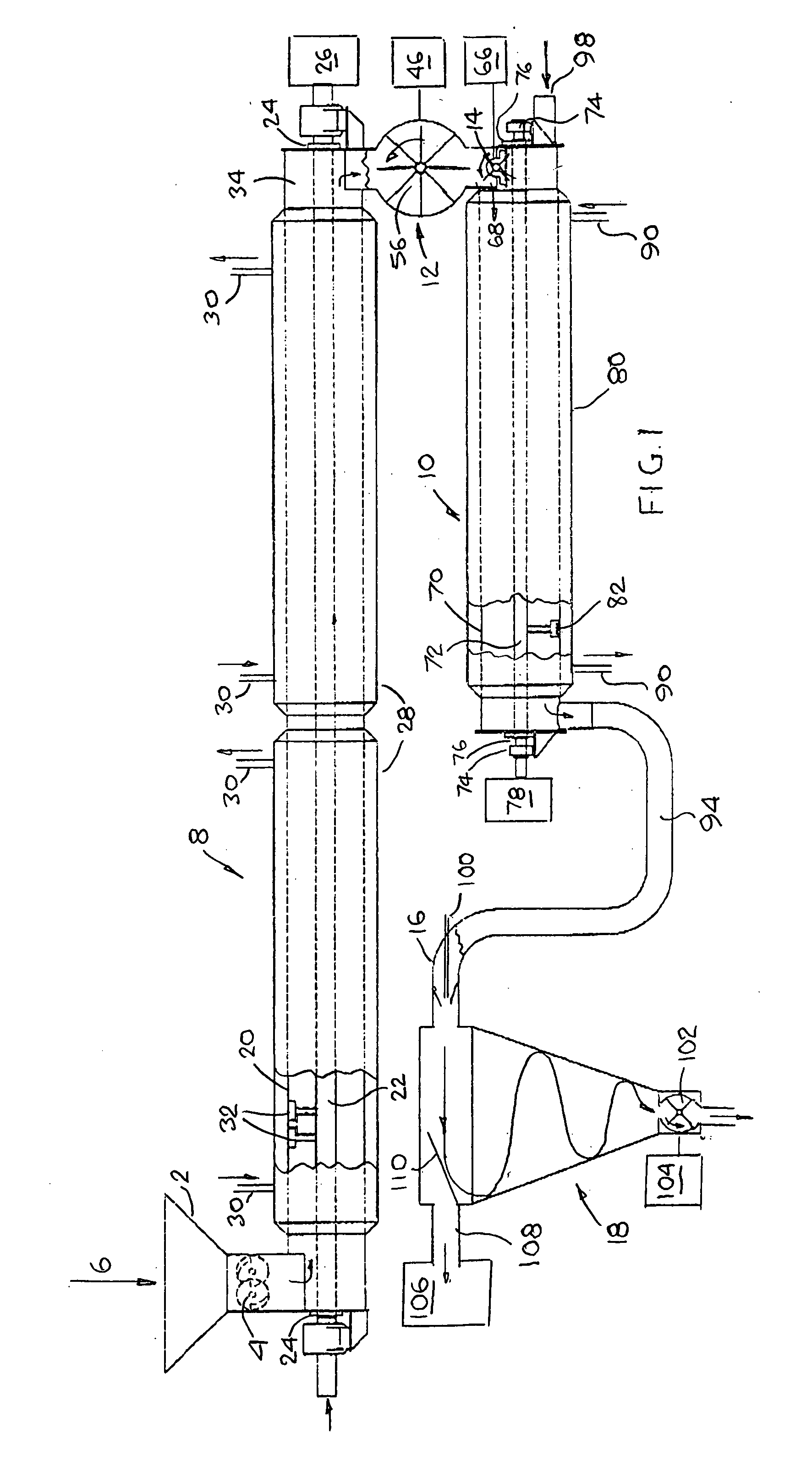
[0031] Referring to FIG. 1, the sludge drying apparatus comprises: a supply hopper 2 which, by way of a rotary shredder 4, can continuously supply sludge entering the hopper 2 in the direction of arrow 6, to a first stage 8 for heating the sludge; a second stage 10 to further heat and to dry the sludge received from the first stage 8 by way of a serially connected rotary transfer lock 12 and a shredder 14; and a cyclonic stage 18 for deodorizing the dry particulate product from the second stage 10 received by way of a venturi 16 located at the input of a cyclonic stage 18.

[0032] The design of the hopper 2 and its rotary shredder 4 will be well known to those of skill in the appropriate art.

[0033] The first stage comprises a tubular housing 20, about 2 feet in diameter and about 30 feet long, concentrically surrounding a hollow shaft 22, about 6 inches in diameter, extending through the length of the tubular housing 20 and beyond the ends thereof by way of seals and bearings 24 for...


PUM


Abstract

A material drying apparatus for substantially eliminating the liquid content of a sludge, the apparatus including a first stage operating at ambient pressure for heating the sludge; a second stage operating with partial vacuum for receiving heated sludge from the first stage for further heating and for drying the sludge by evaporation of substantially all liquid therefrom leaving a dry particulate material; and an evacuated cyclonic stage for applying sufficient centrifugal force to the dry particulate material to render this material odorless.

Description

FIELD OF THE INVENTION [0001] This invention relates to an apparatus and method for drying sludge to produce a substantially dry benign end product e.g. for use as a fertilizer or an innocuous and biologically benign material which can be readily disposed of. DEFINITION [0002] Sludge as used herein shall be construed as including semi-solids, sludges and slurries, e.g. sewage, fecal material, containing evaporable liquids, particularly, though not exclusively, water. BACKGROUND OF THE INVENTION [0003] There are many methods of reducing the moisture content of sludges and slurries containing organic material including filtering using filter presses, heating or chemical treatment or applying partial vacuums. A major concern when using heat and a partial vacuum to dehydrate materials is the high temperature to which the material is heated while exposing the material to an optimum vacuum level. In addition the high temperatures involved tend to reduce or destroy the fertile quality of t...

Claims


Application Information

Patent Timeline
Patent Type & Authority Applications(United States)
IPC IPC(8): F26B5/04F26B17/10F26B17/20
CPCF26B5/041F26B2200/18F26B17/205F26B17/107
Inventor RAGNARSSON, ANDERS T.
Owner RAGNARSSON ANDERS T
Why Eureka
Try Eureka