
Perimeter-cooled stage 1 bucket core stabilizing device and related method

a stabilizing device and bucket core technology, applied in the direction of manufacturing tools, foundry patterns, foundry moulding apparatus, etc., can solve the problems of not being able to simply scale up the stage 2 bucket core for use in the stage 1 and out of tolerance wall thicknesses in the shank portion of the bucket, etc., to achieve stress, particularly at the intersection of printouts

Inactive Publication Date: 2005-01-06
GENERAL ELECTRIC CO
View PDF19 Cites 9 Cited by
  • Summary
  • Abstract
  • Description
  • Claims
  • Application Information

AI Technical Summary

Benefits of technology

[0005] It is also a feature of the present invention that the cross sectional shape of the stabilization devices or printouts is of elliptical rather than the oblong or rounded rectangular shape used with the printouts for the casting of stage 2 buckets. By making the printouts elliptical in cross-sectional shape, the flat surfaces of the prior design have been eliminated, and stresses, particularly at the intersection of the printouts and the core, have been reduced.

Problems solved by technology

In the casting process, however, the core tended to drift significantly, resulting in wall thicknesses in the shank portion of the bucket being out of tolerance.
Because of the different design of the stage 1 and stage 2 buckets, it was not possible to simply scale up the stage 2 bucket core for use in the stage 1 bucket casting process.

Method used


Image

  • Perimeter-cooled stage 1 bucket core stabilizing device and related method
  • Perimeter-cooled stage 1 bucket core stabilizing device and related method
  • Perimeter-cooled stage 1 bucket core stabilizing device and related method

Examples


Embodiment Construction

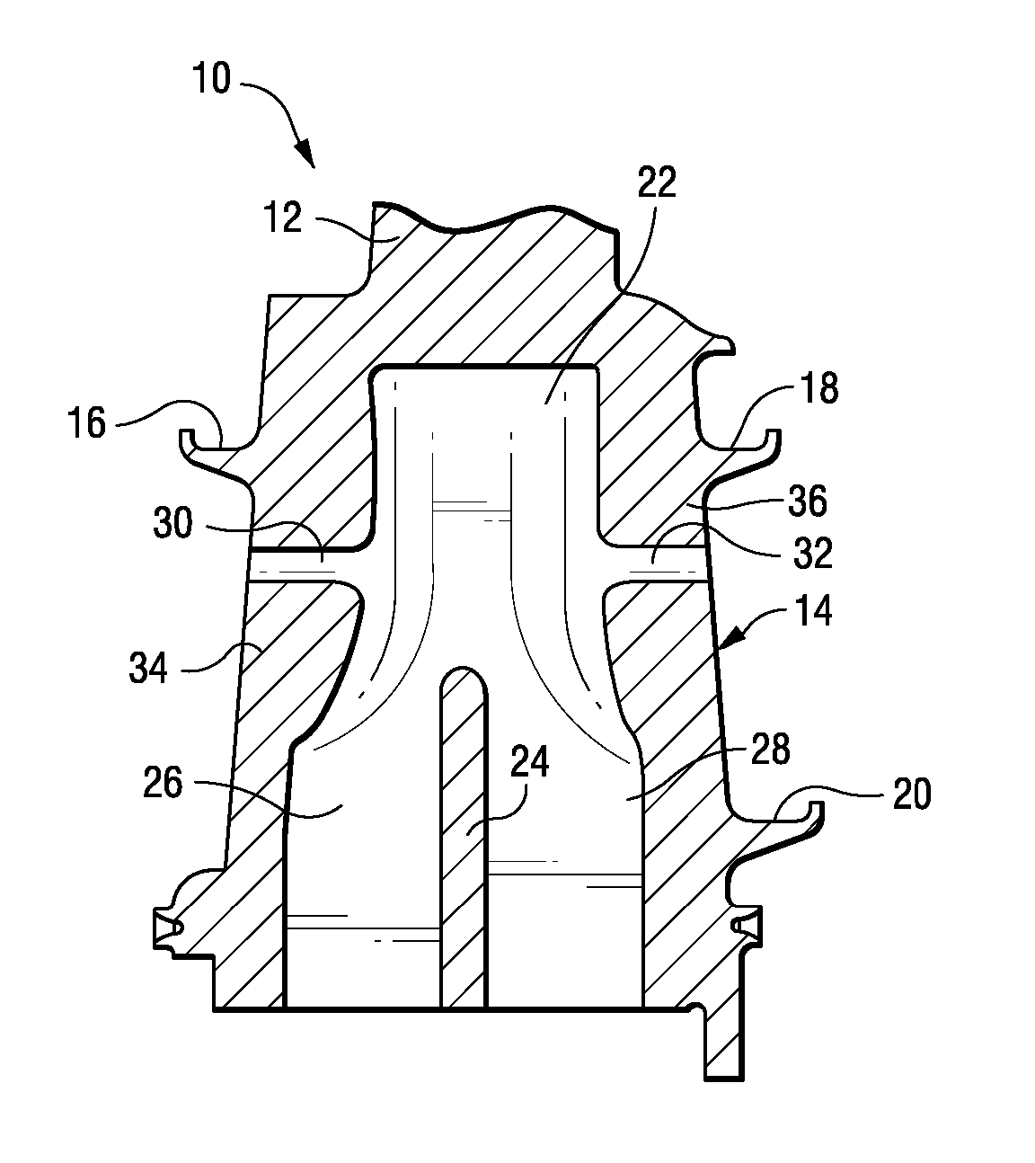
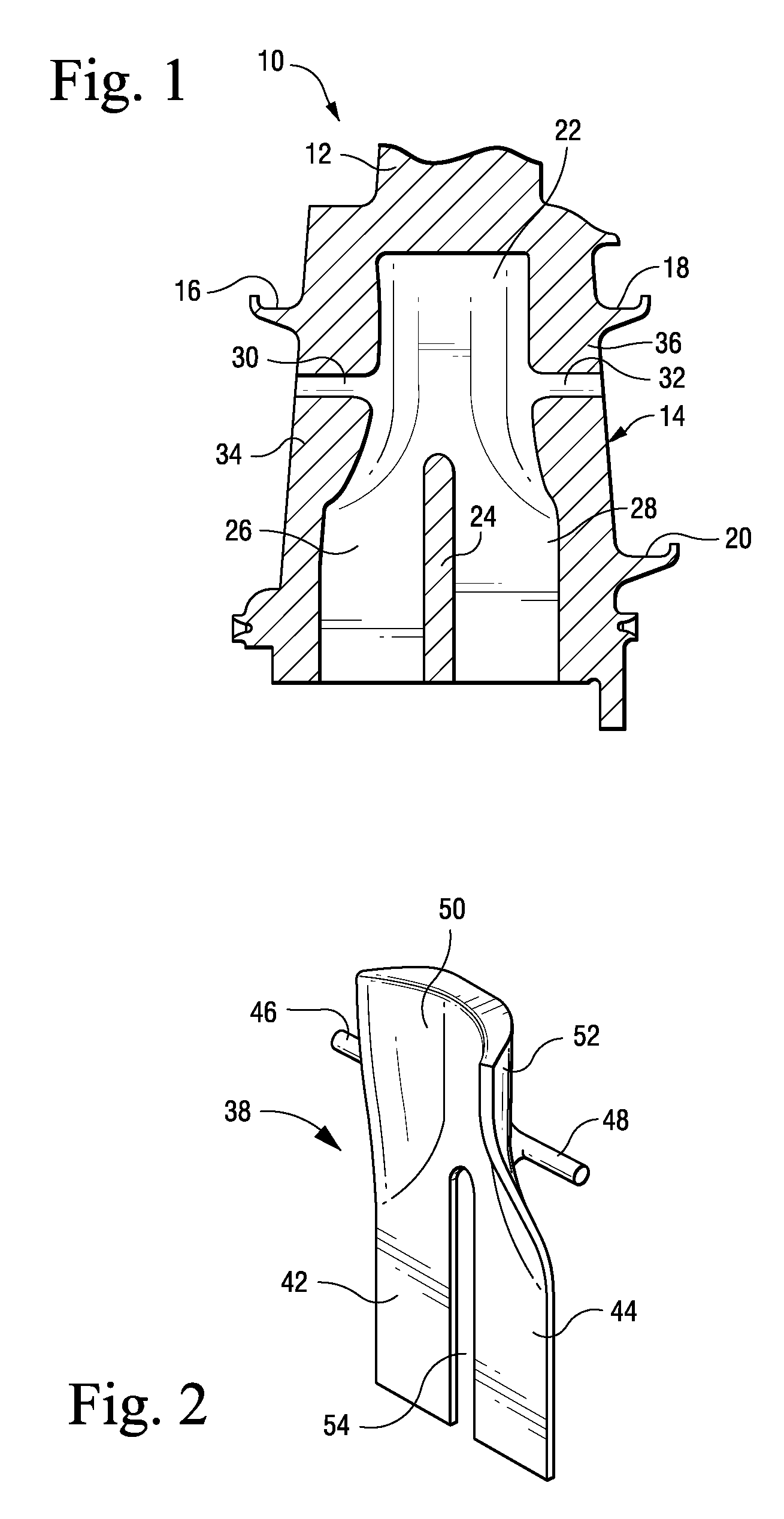
[0015] With reference to FIG. 1, a stage 1 turbine bucket 10 includes an airfoil portion 12 and a shank portion or shank 14. The shank includes a plurality of so-called angel wings 16, 18 and 20 that serve as seals vis-a-vis adjacent buckets when installed on the rotor wheel of a gas turbine. The interior of the shank portion includes a hollow space 22, with a central divider 24 that establishes side-by-side cooling passages 26 and 28. Elliptical holes 30 and 32 are cast in the fore and aft shank walls 34 and 36, respectively, as a byproduct of having the core supported in the shell die during casting.

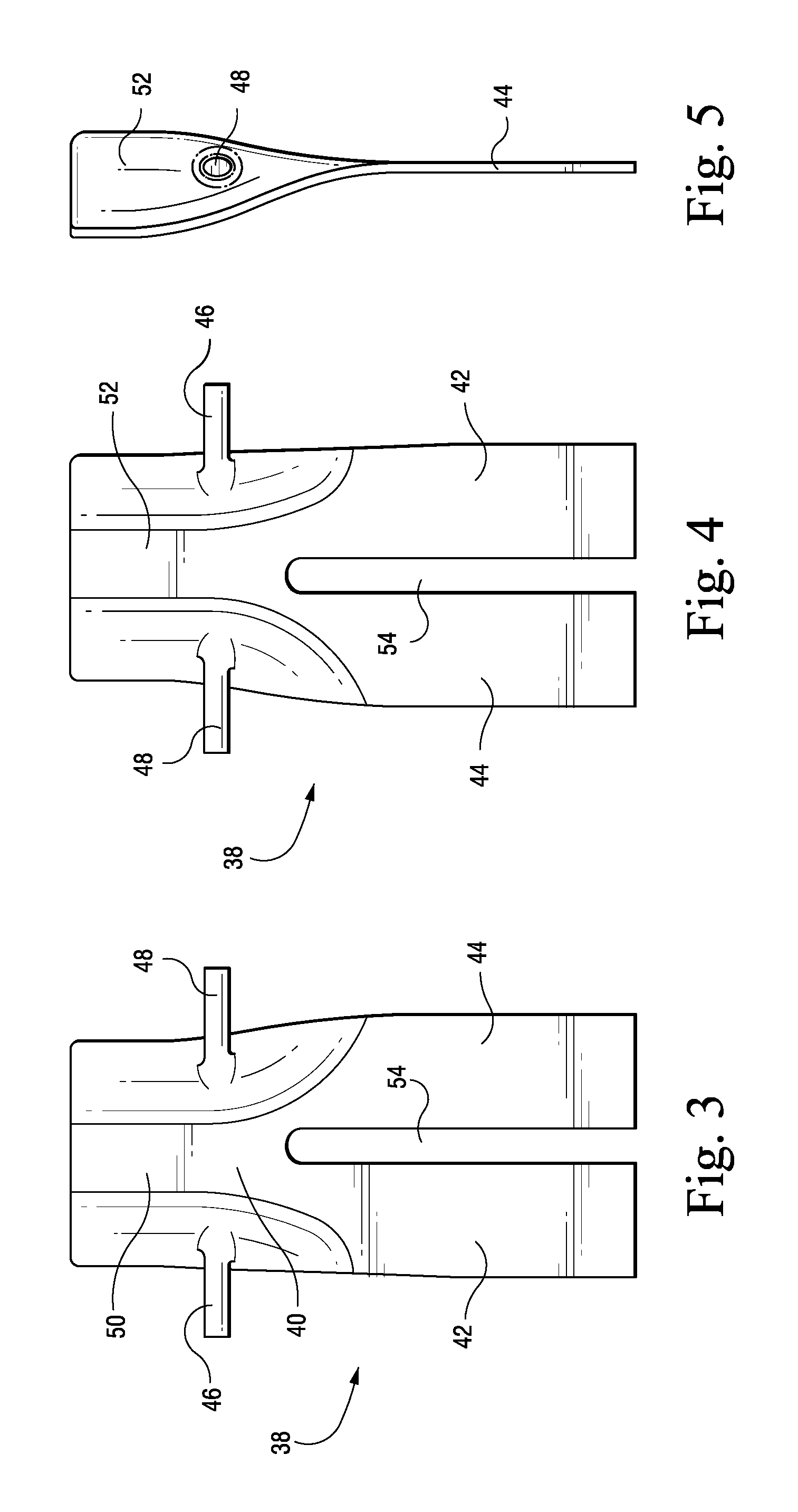
[0016] Turning to FIGS. 2-5, the core 38 has a generally “pants-leg” shape with a solid upper body portion 40 and a pair of radially inwardly extending legs 42 and 44 in accordance with an exemplary embodiment of the invention. A pair of stabilizing pegs or printouts 46, 48 extend axially from opposite sides of the core while an elongated radially extending slot 54 separates the pants...


PUM

PropertyMeasurementUnit
thicknessaaaaaaaaaa
thicknessesaaaaaaaaaa
shapeaaaaaaaaaa

Abstract

A core for use in casting a gas turbine bucket, the core comprising a solid upper body portion and a pair of legs extending downwardly from the solid upper body portion, the pair of legs separated by an elongated slot, and a pair of pegs projecting axially from opposite sides of the upper body portion, above the elongated slot but spaced from an upper edge of the upper body portion.

Description

BACKGROUND OF INVENTION [0001] This invention relates generally to the casting of perimeter-cooled buckets for a gas turbine and, more specifically, to a stabilization device for an internal core used in the bucket casting process. [0002] In an effort to improve the cooling scheme of a stage 1 gas turbine bucket, a “pants-leg” shaped core has been used in the bucket shank portion of the shell die to form a pair of cooling passages in place of a previous design utilized to form a plurality of radial cooling holes. In the casting process, however, the core tended to drift significantly, resulting in wall thicknesses in the shank portion of the bucket being out of tolerance. [0003] Core stabilizing devices or “printouts” for improving the yield of a bucket casting process have been previously used in stage 2 buckets, but with a different core design and in a different location relative to the so-called angel wings on the exterior of the shank portion of the bucket. Because of the diffe...

Claims


Application Information

Patent Timeline
Patent Type & Authority Applications(United States)
IPC IPC(8): B22D45/00B22C9/10B22C9/24B22C21/14B22D27/04
CPCB22C21/14B22C9/10
Inventor BEDDARD, THOMAS BRADLEYPARKS, KENNETH LORENZO
Owner GENERAL ELECTRIC CO
Learn More