Methods and apparatus for handling and drilling with tubulars or casing

a tubular or casing technology, applied in mechanical equipment, sealing/packing, borehole/well accessories, etc., can solve the problems of limiting the load that is actually applied, the top drive connection may be a limiting factor in the load that is applied, and the thread damage of the drill pipe or casing is problematic. , to achieve the effect of reducing the time and labor required for the operation and reducing the cost of the drilling with the casing operation

Inactive Publication Date: 2005-01-06
WEATHERFORD TECH HLDG LLC
View PDF99 Cites 210 Cited by
  • Summary
  • Abstract
  • Description
  • Claims
  • Application Information

AI Technical Summary

Benefits of technology

[0034] Embodiments of the present invention allow a drilling with casing operation, including the drilling operation and the cementing operation, to be conducted by merely changing a lower portion of the apparatus. Embodiments of the present invention eliminate the need to use a separate cementing tool for the cementing operation, thus reducing the time and labor required for the operation. Consequently, the cost of the drilling with casing operation is reduced.

Problems solved by technology

A problem encountered with top drive systems is the potential for damage to the threads of the drill pipe or casing.
Damage to the casing threads is problematic because the casing connections must remain fluid and pressure tight once the drilling operation has been completed.
Therefore, the top drive connection may be a limiting factor in the load that is actually applied.
For example, the connection between the top drive and the torque head may limit the tensile load supportable by the top drive.
The problem is exacerbated when drilling with casing because a casing typically weighs more than a drill pipe.
Therefore, the drilling with casing operation may be prematurely stopped because the weight and drag of the casing drill string exceeded the tensile load rating of the top drive connection.
While many drilling apparatus may be redesigned with a larger size threaded connection to increase its tensile load capacity, it is very costly and inefficient to redesign or replace a top drive already existing on a rig.
Failure to circulate drilling fluid while drilling into the formation may cause the drill string to stick within the wellbore; therefore, it is necessary for a fluid circulation path to exist through the drill string being drilled into the formation.
Extra time results in extra labor and money spent on the operation.

Method used


Image

  • Methods and apparatus for handling and drilling with tubulars or casing
  • Methods and apparatus for handling and drilling with tubulars or casing
  • Methods and apparatus for handling and drilling with tubulars or casing

Examples


Embodiment Construction

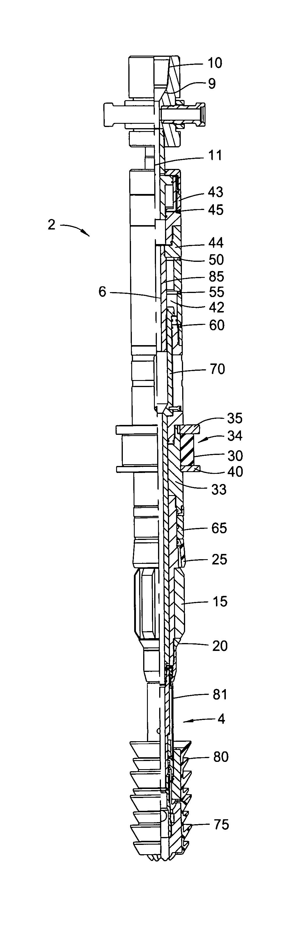
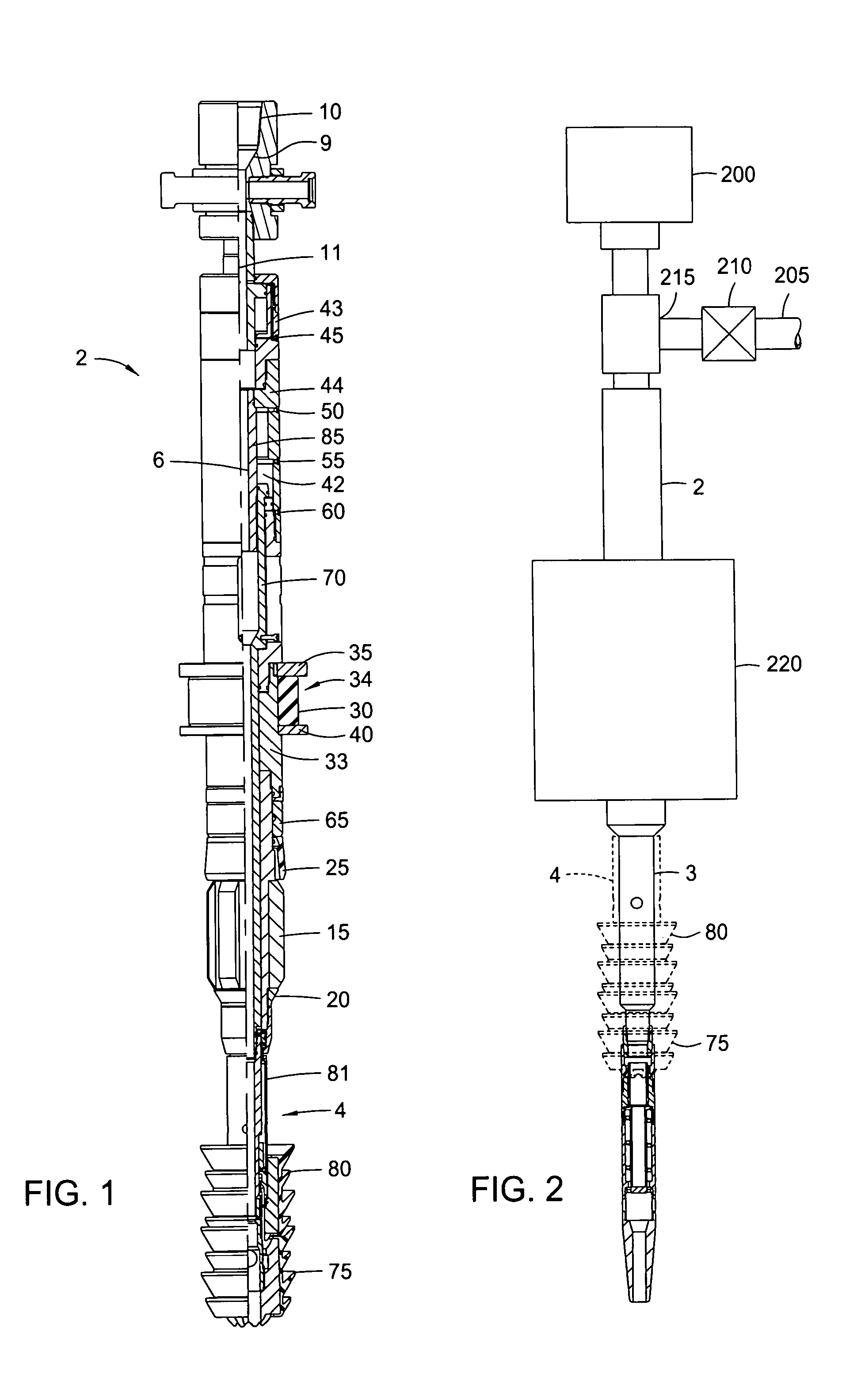
[0061]FIG. 1 is a combination circulation / cementing tool 2 according to the present invention. The tool 2 has a tubular-shaped plug release mandrel 85 with a longitudinal bore therethrough. A sub 9 located at an upper portion of the tool 2 connects a lower portion of a connector mandrel 11 to an upper portion of the tool 2. Threads 10 are located at an upper end of the sub 9 so that the tool 2 is capable of connection to other tools such as a top drive 200 (see FIG. 2). Any other connection means known to those skilled in the art may be utilized in lieu of threads.

[0062] Connected to a lower end of the connector mandrel 11 by at least one sealing member such as an O-ring is a tubular-shaped releasing body 43 with a longitudinal bore therethrough. The releasing body 43 has a plug release 45 located thereon. The releasing body 43 allows the shorting of the tool 2 to release the slips on either the torque head or spear (described below) in case of a hydraulic lock.

[0063] An upper end...


PUM


Abstract

The present invention provides a method and apparatus for handling tubulars and drilling with tubulars such as casing into a formation. In one aspect of the invention, the apparatus comprises a circulating head and a cementing head operatively connectible to a gripping member. The circulating head is used to circulate drilling fluid while drilling with casing, and the cementing head is used to cement the casing string within the formation at a desired depth. The present invention also relates to methods and apparatus for isolating a tensile load from a drilling apparatus rotated by a top drive. In one aspect, the present invention provides a load isolator apparatus having an isolator body operatively connected to the top drive and a torque body at least partially disposed in the isolator body. In operation, the bearing assembly transfers the tensile load from the torque body to the isolator body.

Description

CROSS-REFERENCE TO RELATED APPLICATIONS [0001] This application is a continuation-in-part of co-pending U.S. patent application Ser. No. 10 / 389,483 filed Mar. 14, 2003, which is herein incorporated by reference in its entirety. U.S. patent application Ser. No. 10 / 389,483 is a continuation of U.S. patent application Ser. No. 09 / 550,721 filed on Apr. 17, 2000, now U.S. Pat. No. 6,536,520, which is also herein incorporated by reference in its entirety. [0002] This application claims benefit of U.S. Provisional Patent Application Ser. No. 60 / 452,192 fled on Mar. 5, 2003, which is herein incorporated by reference in its entirety. This application further claims benefit of U.S. Provisional Patent Application Ser. No. 60 / 452,156 filed on Mar. 5, 2003, which is herein incorporated by reference in its entirety.BACKGROUND OF THE INVENTION [0003] 1. Field of the Invention [0004] Embodiments of the present invention generally relate to handling tubulars and drilling into a formation to form a w...

Claims


Application Information

Patent Timeline
Patent Type & Authority Applications(United States)
IPC IPC(8): E21B3/02E21B19/07E21B19/16E21B21/02E21B33/04E21B33/05
CPCE21B7/20E21B19/07E21B19/16E21B19/165E21B19/166Y10T74/1558E21B21/02E21B33/0422E21B33/05E21B33/14E21B21/00
Inventor GIROUX, RICHARD L.SHAHIN, DAVIDVUYK, ADRIAN JR.THOMPSON, GARYGRAY, KEVIN LEONALLEN, JOHN TIMOTHYSNIDER, RANDY GENE
Owner WEATHERFORD TECH HLDG LLC
Why Eureka
Try Eureka