Pneumatic nailer

a nailer and pneumatic technology, applied in the direction of nails, nailing tools, fastening means, etc., can solve the problems of reducing affecting the aesthetic appeal of the nailer, so as to reduce the force of unwanted impacts

Inactive Publication Date: 2005-01-06
MILWAUKEE ELECTRIC TOOL CORP
View PDF99 Cites 79 Cited by
  • Summary
  • Abstract
  • Description
  • Claims
  • Application Information

AI Technical Summary

Benefits of technology

[0010] In some aspects and in some constructions, the invention provides a nailer, such as a pneumatic nailer, that generally includes a bumper disposed therearound to decrease the force of unwanted impacts on the nailer caused by, for example, dropping the nailer, setting down the nailer, etc.

Problems solved by technology

In the workplace, nailers may often be subject to unwanted forces caused by, for example dropping the nailer, stepping on the nailer, or otherwise impacting the nailer / components of the nailer.
All of these unwanted forces can damage the housing of the nailer and / or the internal components of the nailer.
Damaging the housing decreases the aesthetic appealability of the nailer and can cause the nailer to operate incorrectly or to not operate at all.
Exhausted air may exhaust in an undefined or less-than-preferred direction from the nailer (e.g., may exhaust at the operator (into the operator's face, at the operator's body)) and may cause discomfort to the operator or affect the operation of the nailer.
Exhausted air can also blow particles, such as, for example dust, dirt, saw dust, debris, etc., in unwanted directions around the work area, such as, for example at the operator (into the operator's face), onto the workpiece, or randomly into the air, to cause discomfort to an operator, to affect operation of the nailer or to simply make a mess of the work area.
Fasteners may be incorrectly loaded into some conventional nailers.
Nailers typically have magazines into which fasteners may be incorrectly inserted by an unwary or inattentive operator.
If the bundle, stick or set of collated fasteners is inserted incorrectly, the leading fastener may not be properly aligned with the drive assembly and can be driven in the incorrect orientation or in an incorrect direction.
Driving the leading fastener in the improper orientation / direction may damage the nailer, such as, for example, damaging the drive assembly, driving the nail through a wall of the magazine or other portion of the nailer, may damage the workpiece or surrounding equipment or may cause an injury to an operator.
Conventional nailers typically do not prevent the conventional nailer from firing when the collated fasteners are inserted incorrectly.

Method used


Image

  • Pneumatic nailer
  • Pneumatic nailer
  • Pneumatic nailer

Examples


Embodiment Construction

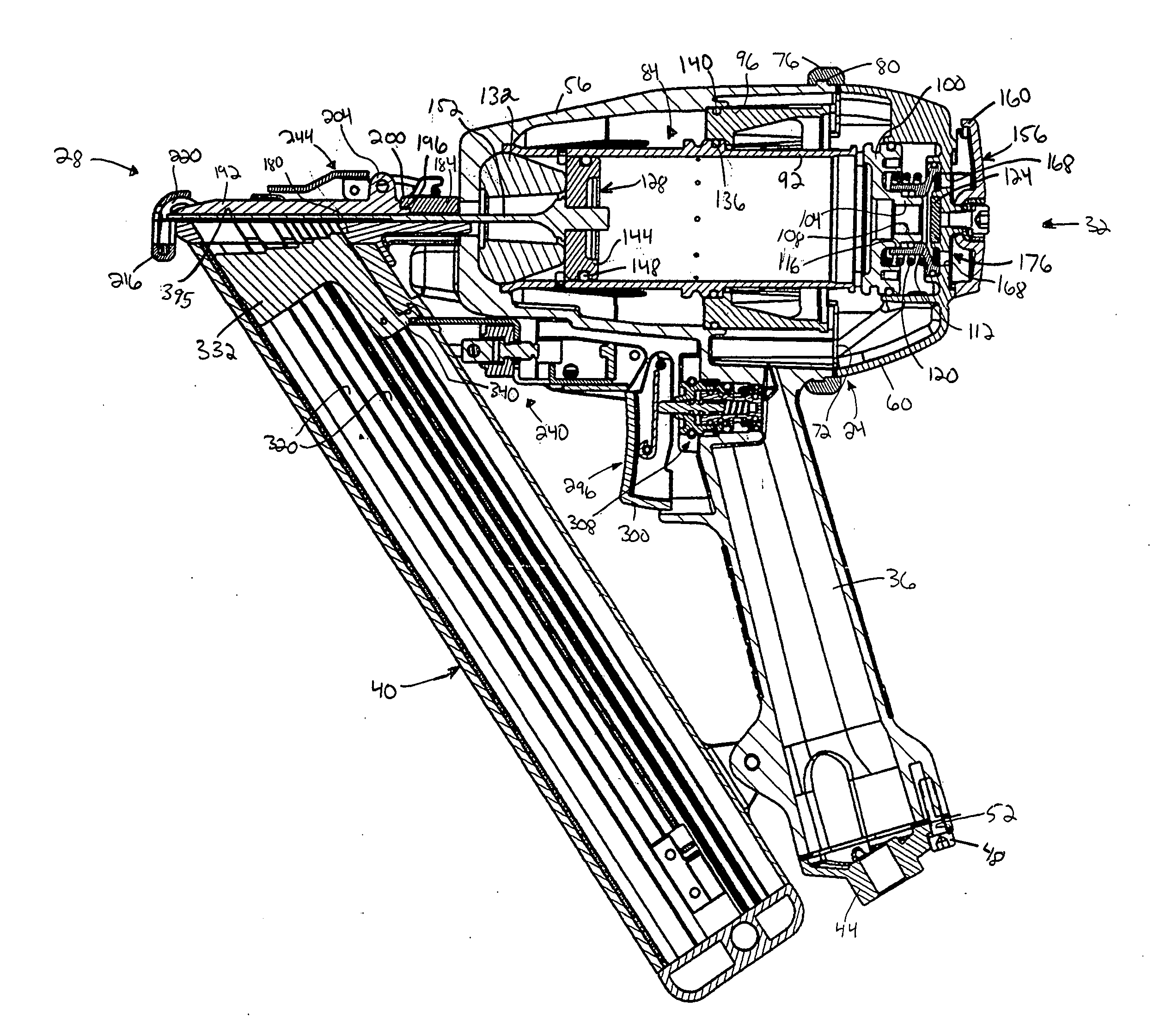
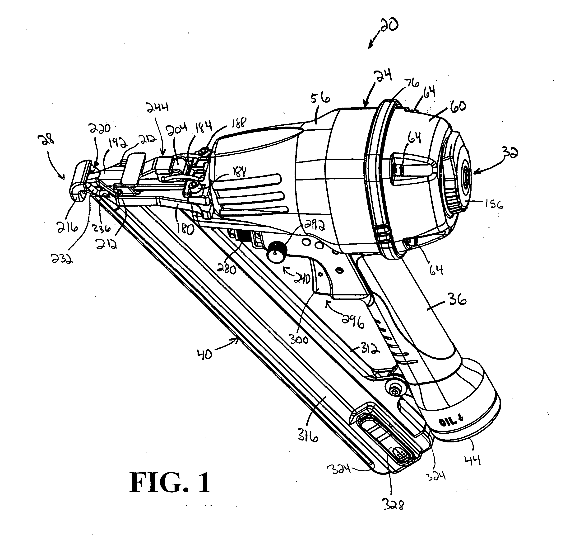
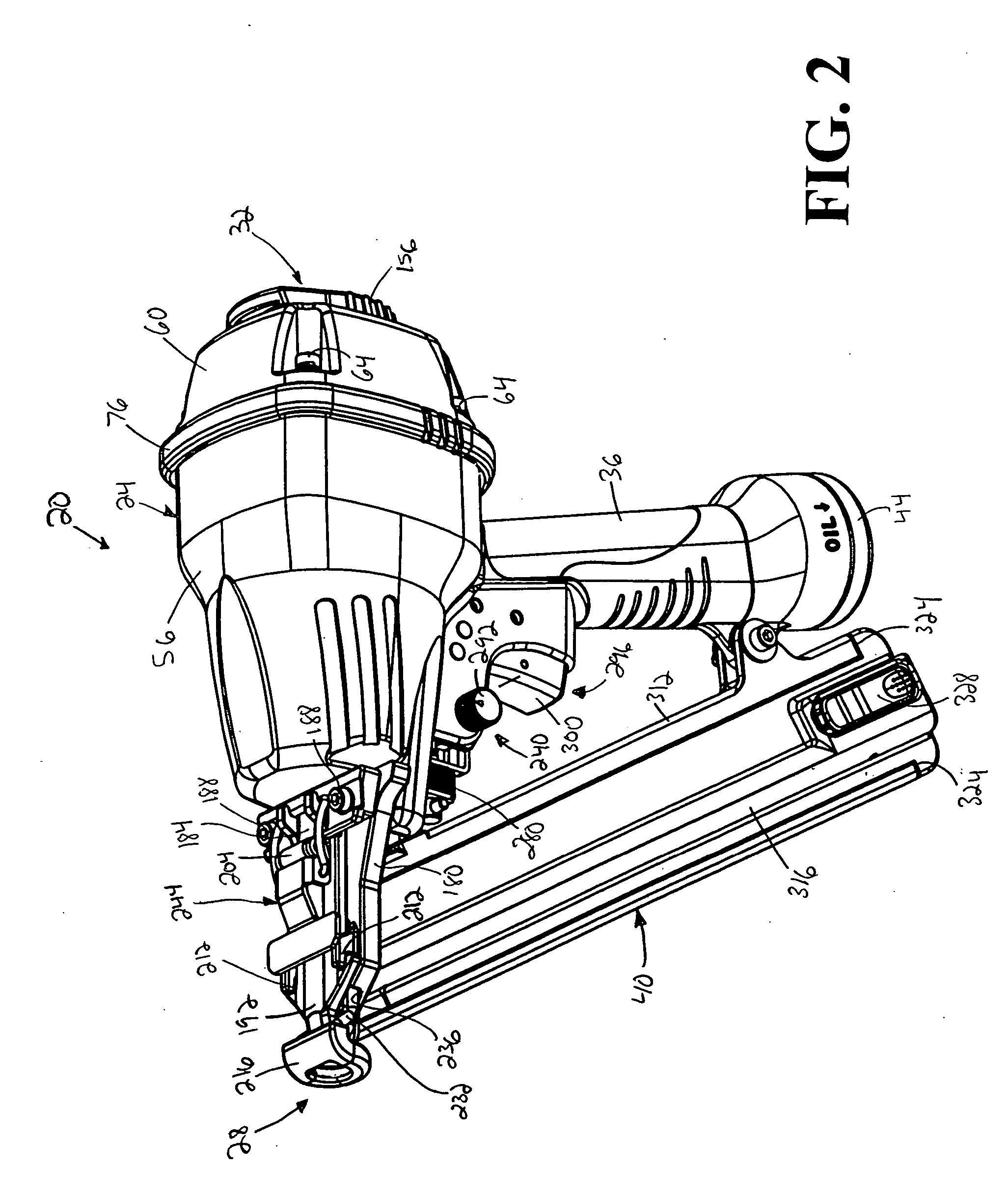
[0078] A power tool, such as a pneumatic air-powered nailer 20, embodying independent aspects of the present invention, is illustrated in FIGS. 1-15. It should be understood that, in other constructions and in other aspects, the power tool can be another type of nailers, such as, for example, a combustion nailer, an electric powered nailer, etc. Also, it should be understood that, in other constructions and in other aspects, the power tool can be another type of power tool, such as, for example, a drill, a screwdriver, a saw, etc.

[0079] Referring to FIGS. 1-12, the nailer 20 is a “finish”-type nailer and includes a body 24 having a forward end 28 and a rearward end 32, a handle 36 extending from the rearward end 32 and a magazine 40 connected to the forward end 28 and the handle 36. A coupling 44 is positioned at an end of the handle 36 to couple a supply line (not shown), which supplies air from a pneumatic source (not shown), to the nailer 20. Connecting members 48 are disposed o...


PUM


Abstract

Power tools, nailers and strips of fasteners. In some aspects and in some constructions, the invention may provide a power tool including a housing, a deflector selectively movable relative to the housing between a first position, in which the deflector deflects fluid in a first direction, and a second position, in which the deflector deflects fluid in a second direction. In some aspects and in some constructions, the invention may provide a nailer including a magazine operable to support a strip of fasteners in an orientation therein, the magazine defining an insertion opening therein through which the strip of fasteners is insertable into the magazine, the insertion opening having a configuration, the strip of fasteners having a configuration complementary to the configuration of the insertion opening, the strip of fasteners insertable into the magazine only when the strip of fasteners is in the orientation.

Description

RELATED APPLICATIONS [0001] The present application claims the benefit of prior-filed, co-pending provisional patent application Ser. No. 60 / 474,710, filed May 29, 2003, the contents of which is hereby incorporated by reference.FIELD OF THE INVENTION [0002] The present invention relates to power tools and, more particularly, to pneumatic nailers. SUMMARY OF THE INVENTION [0003] Conventional nailers, such as pneumatic nailers and combustion nailers, are operable to drive fasteners into workpieces. Such nailers typically include a housing for supporting a drive assembly, a handle, a trigger assembly connectable to the drive assembly to cause firing of the drive assembly, a magazine for supporting fasteners therein and a power source, such as a pneumatic source or a combustion device, operable to power the drive assembly and drive fasteners into a workpiece. [0004] In the workplace, nailers may often be subject to unwanted forces caused by, for example dropping the nailer, stepping on ...

Claims


Application Information

Patent Timeline
Patent Type & Authority Applications(United States)
IPC IPC(8): B25C1/00B25C1/04F16B15/08F16B23/00
CPCB25C1/005B25C1/008F16B23/0007B25C1/047F16B15/08B25C1/041
Inventor BUTZEN, ROBERT W.MEYER, GARY D.JUNGMANN, RICHARD H.OTTENS-RENDON, MELISSANEITZELL, ROGER D.
Owner MILWAUKEE ELECTRIC TOOL CORP
Why Eureka
Try Eureka