Method for producing multilayer optical recording medium and system for production multilayer optical recording medium

a multi-layer optical recording medium and optical recording medium technology, applied in the field of system for producing multi-layer optical recording medium, can solve the problems of troublesome center pin cleaning, difficult to effect uniform coating, difficult to perform normal reading and writing of record data, etc., to prevent air bubble intrusion, improve the effect of this point, and high manufacturing cos

Inactive Publication Date: 2005-01-06
TDK CORPARATION
View PDF0 Cites 11 Cited by
  • Summary
  • Abstract
  • Description
  • Claims
  • Application Information

AI Technical Summary

Benefits of technology

[0007] From the study of the above described methods of manufacturing a multilayer optical recording medium, the present inventors found out the following points for improvement: In the former manufacturing method, after completion of spin-coating of the coating liquid R, the stamper 51 is placed over the substrate D coated with the coating liquid R. In this case, when the stamper 51 in the form of a flat plate is placed over the substantially evenly applied coating liquid R, air bubbles can intrude between the coating liquid R and the stamper 51. When ultraviolet rays are applied in this state, large recesses are formed in t...

Problems solved by technology

When ultraviolet rays are applied in this state, large recesses are formed in the surface of the spacer layer S due to intrusion of the air bubbles, which makes it difficult to perform normal reading and writing of record data.
In spin-coating, the presence of the space makes the coating thickness of the coating liquid R on the radially outermost portion of the substrate D larger than that on the radially innermost portion of the same, which makes it difficult to effect uniform coating of the coating liquid R. In this case, it is possible to apply the coating liquid R onto...

Method used


Image

  • Method for producing multilayer optical recording medium and system for production multilayer optical recording medium
  • Method for producing multilayer optical recording medium and system for production multilayer optical recording medium
  • Method for producing multilayer optical recording medium and system for production multilayer optical recording medium

Examples


Embodiment Construction

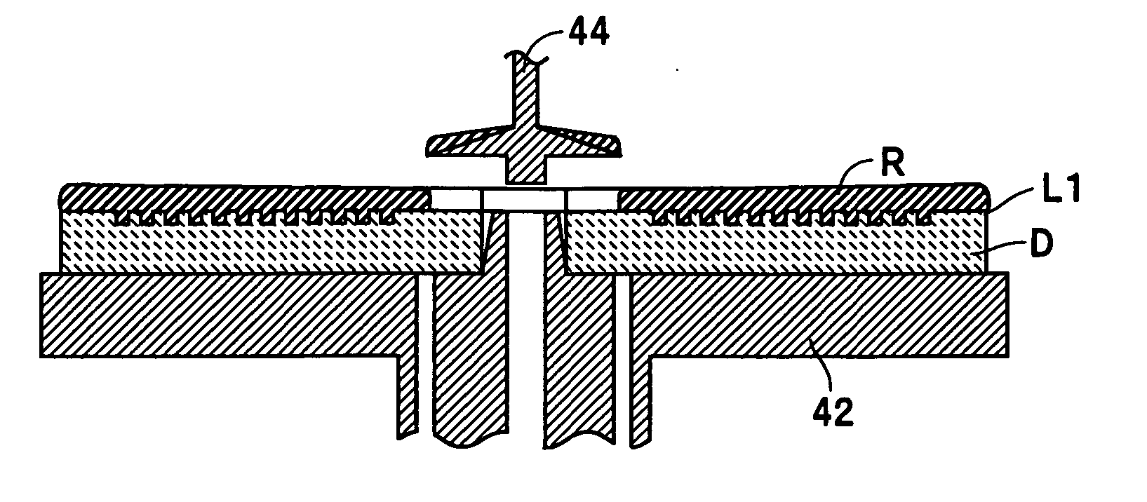
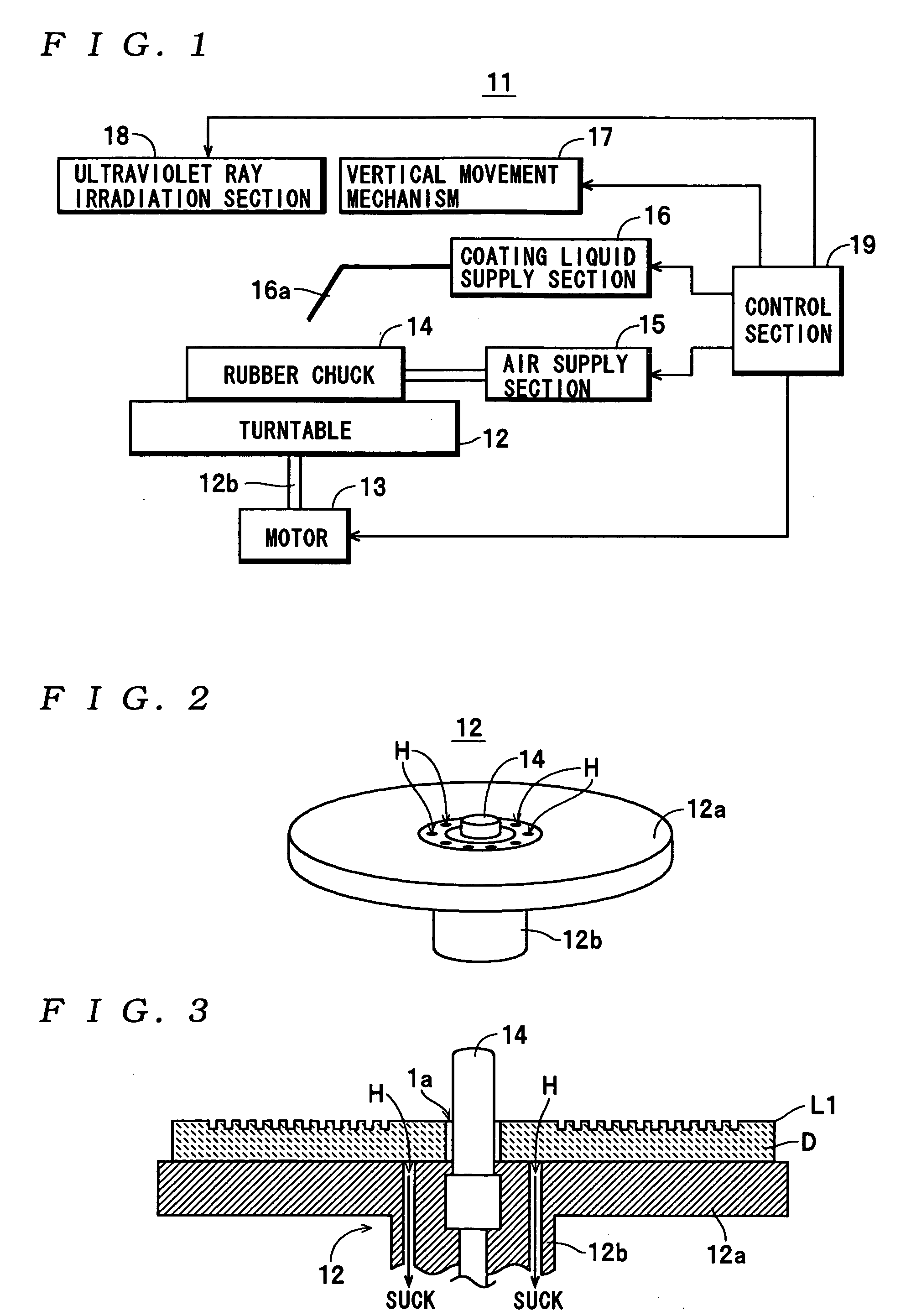
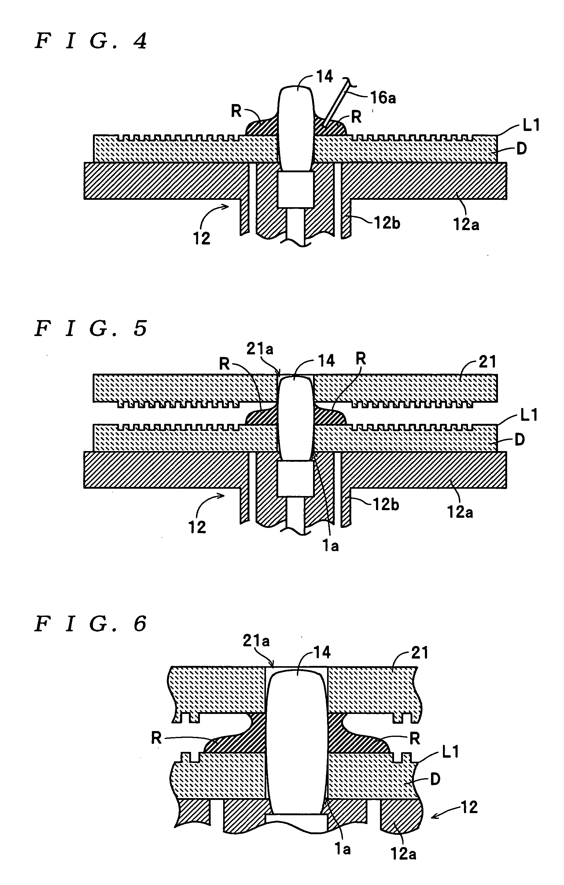
[0038] Hereinafter, preferred embodiments of a method of manufacturing a multilayer optical recording medium and a multilayer recording medium-manufacturing apparatus, according to the present invention, will be described with reference to the accompanying drawings.

[0039] First of all, the structure of the multilayer optical recording medium 1 will be described with reference to FIG. 12.

[0040] The multilayer optical recording medium 1 is constructed by sequentially depositing a recording layer L1 corresponding to an (M+1)-th (M=1) recording layer in the present invention, a spacer layer S, a recording layer L0 corresponding to an M-th recording layer (M=1) in the present invention, and a cover layer C, on a substrate D, such that record data can be read or recorded by applying a laser beam set to a reproducing power or a laser beam set to a recording power, onto the multilayer optical recording medium 1 from a cover layer C side. The substrate D is formed by injection molding such...


PUM


Abstract

A method of manufacturing a multiplayer optical recording medium by depositing two recording layers, with a spacer layer sandwiched therebetween, on a substrate. The method includes using a rubber chuck which can undergo elastic deformation at least in radial directions to close a central mounting hole of the substrate to thereby fix the substrate having the recording layer formed thereon on a turntable. After a coating liquid for forming the spacer layer is dropped in the vicinity of a boundary portion between a peripheral surface of the rubber chuck and the substrate, the rubber chuck is caused to chuck a stamper for forming the first recording layer thereon while allowing the stamper to be placed over the substrate. Thereafter, the turntable is rotated to spin-coat the coating liquid. This makes it possible to form a spacer layer having a uniform layer thickness while preventing intrusion of air bubbles, without leading to high manufacturing costs.

Description

TECHNICAL FIELD [0001] This invention relates to a method of manufacturing a multilayer optical recording medium having a plurality of recording layers deposited with a spacer layer sandwiched therebetween, and a multilayer recording medium-manufacturing apparatus. BACKGROUND ART [0002] The present applicant has developed a multilayer optical recording medium 31 shown in FIG. 12 as one of the above-mentioned kind. This multilayer optical recording medium 31 has a recording layer L1, a spacer layer S, a recording layer L0, and a cover layer C sequentially deposited on a disk-shaped substrate D having a mounting central hole 1a formed through a central portion thereof. In this multilayer optical recording medium 31, the recording layer L1 is comprised of a reflective film for reflecting a laser beam set to a recording power and applied for recording and a laser beam set to a reproducing power and applied for reproduction (each of which is hereinafter also simply referred to as “the la...

Claims


Application Information

Patent Timeline
IPC IPC(8): G11B7/26B29D17/00G11B7/24
CPCB29D17/005G11B7/24038G11B7/266G11B7/265G11B7/263
Inventor KOMAKI, TSUYOSHIUSAMI, MAMORUYONEYAMA, KENJI
Owner TDK CORPARATION
Why Eureka
Try Eureka