Satellite antenna mounting apparatus and method

Inactive Publication Date: 2005-01-06
ANTOINE MARK J
View PDF10 Cites 31 Cited by
  • Summary
  • Abstract
  • Description
  • Claims
  • Application Information

AI Technical Summary

Benefits of technology

[0006] In view of the foregoing background, it is therefore an object of the present invention to provide a mounting apparatus and method for easily and inexpensively securing a satellite antenna to a building. It is f

Problems solved by technology

Mounting on what is typically a pitched roof often results in diminishing the integrity of the roof causing leaks as a result of drilling through the roofing material into rafters for obtaining structural integrity for the mount

Method used


Image

  • Satellite antenna mounting apparatus and method
  • Satellite antenna mounting apparatus and method
  • Satellite antenna mounting apparatus and method

Examples


Embodiment Construction

[0027] The present invention will now be described more fully with reference to the accompanying drawings in which preferred embodiments of the invention are shown and described. It is to be understood that the invention may be embodied in many different forms and should not be construed as limited to the illustrated embodiments set forth herein. Rather, the applicant provides these embodiments so that this disclosure will be thorough and complete, and will convey the scope of the invention to those skilled in the art. Like numbers refer to like elements there through.

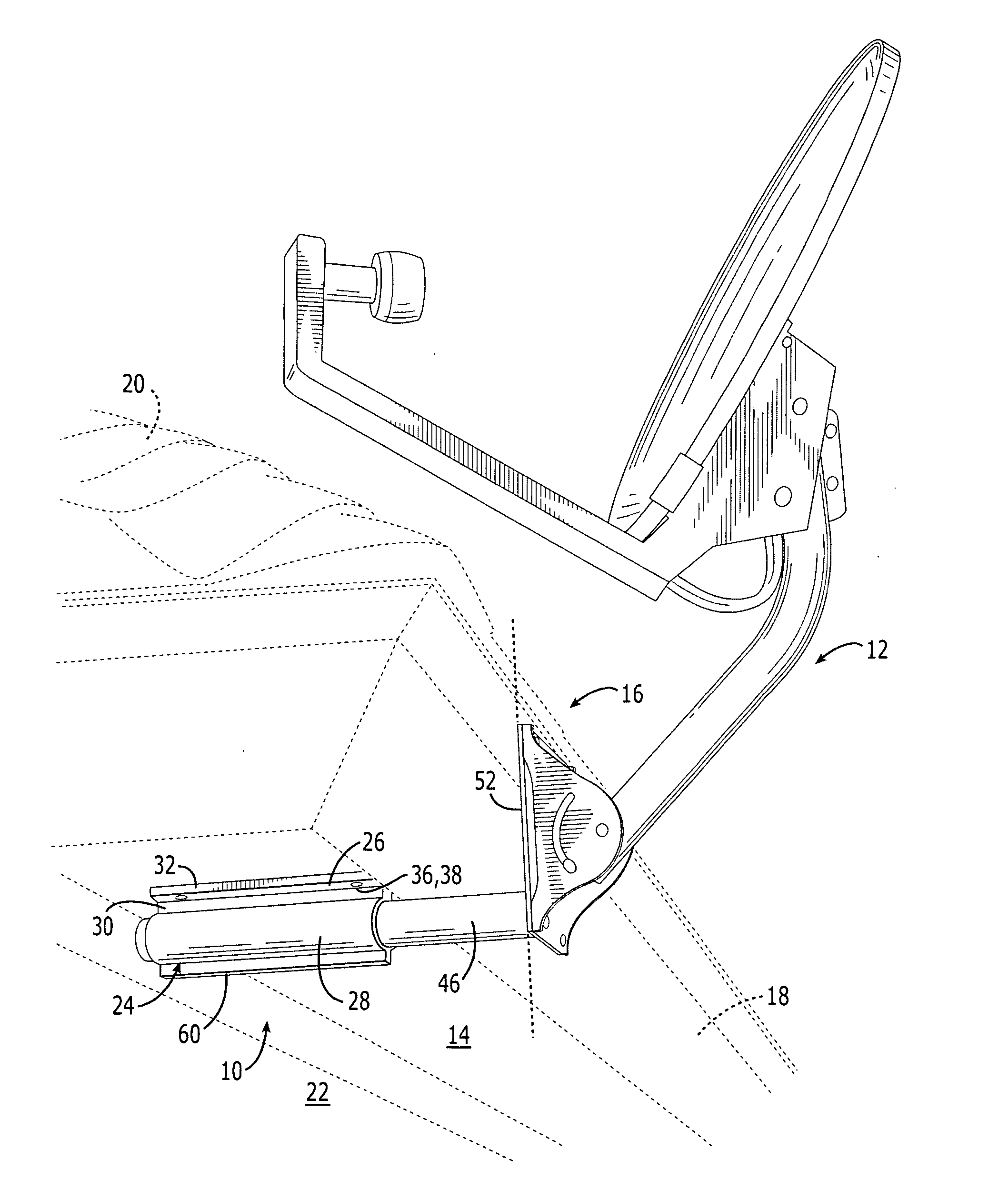
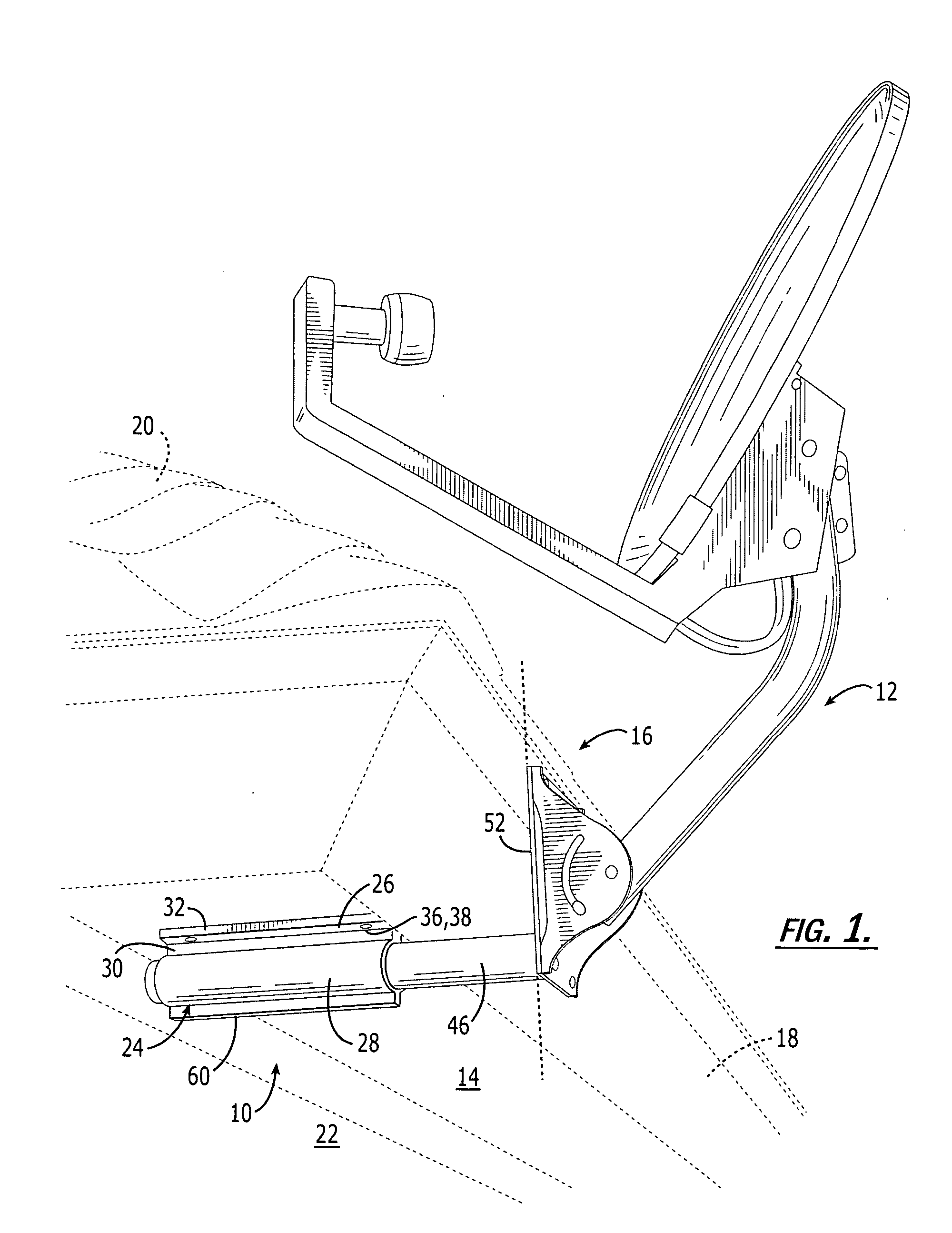
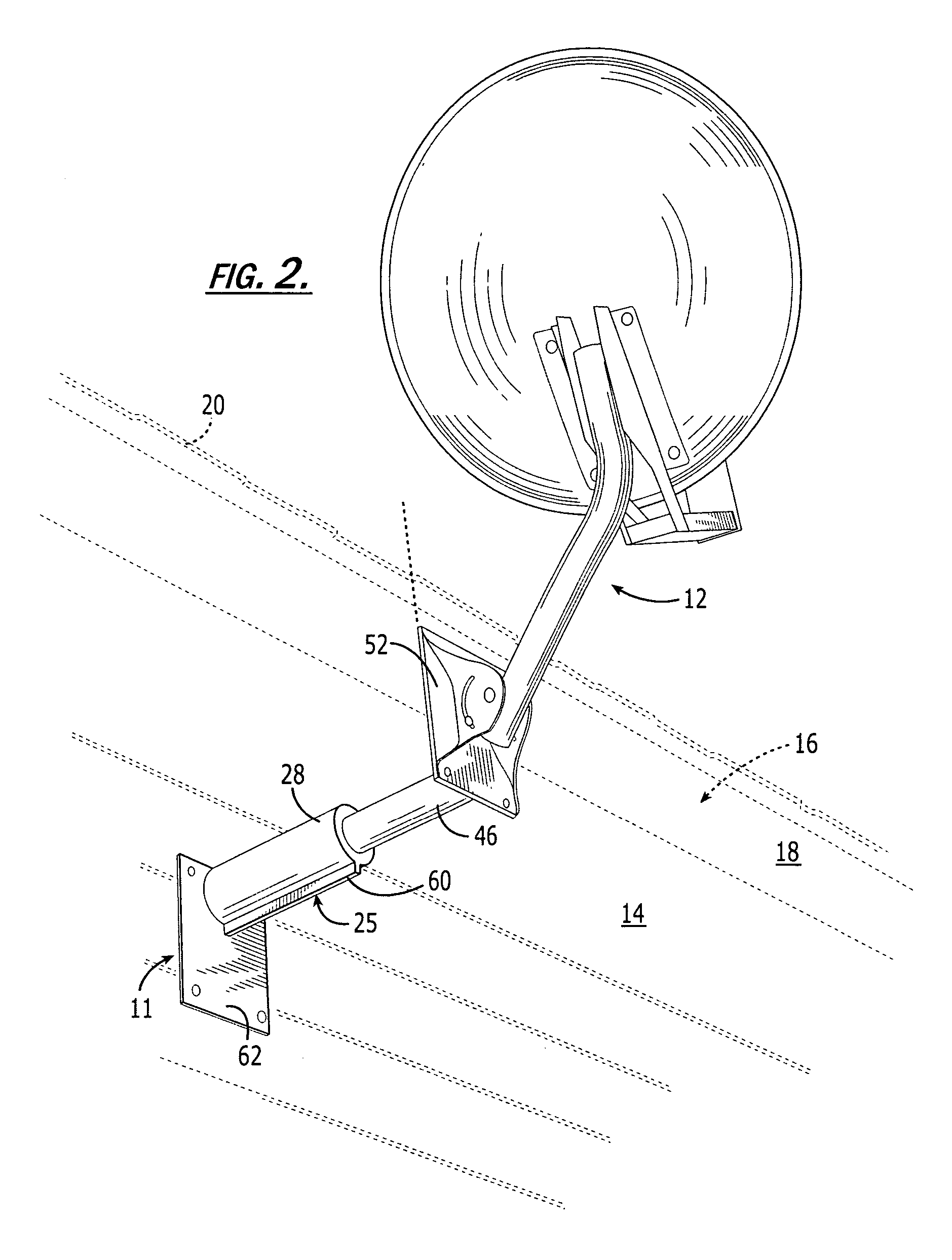
[0028] As illustrated initially with reference to FIG. 1, one embodiment of the present invention includes a mounting bracket 10, an apparatus for mounting a satellite antenna dish assembly 12 to a soffit 14 of a building 16 for supporting the assembly 12 from the soffit and extending it beyond the fascia 18 and edge of the roof 20. An alternate embodiment of the present invention includes a bracket 11 mounted to a si...


PUM


Abstract

A mounting bracket includes a single mount for attaching to the soffit of a building for adjustably carrying a satellite dish antenna. The mount includes a base having holes for receiving screws to secure the mount to structural members such as studs or trusses to which the soffit is attached. A body portion of the mount includes a bore for receiving an arm of the mounting bracket. One end of the arm includes a plate adapted for attaching the arm to a satellite antenna dish assembly. Once the arm is positioned within the mount, setscrews lock the arm in its desired place within the bore, thus securing the satellite antenna to a desired location on the soffit.

Description

CROSS-REFERENCE TO RELATED APPLICATIONS [0001] This application is a continuation of U.S. application Ser. No. 10 / 038,755, filed Dec. 31, 2001, the disclosure of which is hereby incorporated herein in its entirety by reference.FIELD OF THE INVENTION [0002] This application is generally related to antenna mounting brackets and more particularly to a telescoping bracket for mounting and aligning a satellite antenna disk. BACKGROUND OF THE INVENTION [0003] While the physical size required of satellite dish antennas for receiving clear audio and video signals has decreased as a result of increased satellite receiver sensitivity, the reduced size has made it desirable to mount satellite antennas on a building such as a residence. Typically, an unobstructed view of an appropriate satellite operable with the antenna is achieved by mounting the antenna on the roof or sidewall of the building. Mounting on what is typically a pitched roof often results in diminishing the integrity of the roof...

Claims


Application Information

Patent Timeline
IPC IPC(8): H01Q1/12
CPCH01Q1/1207H01Q1/12
Inventor ANTOINE, MARK J.
Owner ANTOINE MARK J
Why Eureka
Try Eureka