Abnormal state occurrence predicting method, state deciding apparatus, and image forming system

a technology of state deciding apparatus and abnormal state, applied in the field of image forming system, can solve the problems of user suffering time loss, all or some of the functions of the apparatus must be stopped, and the user cannot predict the time for occurrence of abnormal sta

Inactive Publication Date: 2005-01-06
RICOH KK
View PDF99 Cites 68 Cited by
  • Summary
  • Abstract
  • Description
  • Claims
  • Application Information

AI Technical Summary

Benefits of technology

It is an object of the invention to at least solve the problems in the conventional technology.

Problems solved by technology

When a failure occurs, all or some of the functions of the apparatus must be stopped until repair is finished, and a user has to suffer a time loss.
However, the above method can predict the possibility of occurrence of an abnormal state, but cannot predict a time for occurrence of the abnormal state.

Method used


Image

  • Abnormal state occurrence predicting method, state deciding apparatus, and image forming system
  • Abnormal state occurrence predicting method, state deciding apparatus, and image forming system
  • Abnormal state occurrence predicting method, state deciding apparatus, and image forming system

Examples


second embodiment

In the following explanation related to the first and the second embodiment modes, signs described below are used.

When height from an optical axis is assumed to be H, an aspherical surface is defined by the following expression assuming that a displacement amount in an optical axis direction from a surface vertex is S, a curvature radius is R, and an aspherical coefficient is A2i. S=(1 / R)×H21+1-(1 / R)2×H2+∑i⁢Asi×H2⁢i(3)

FIGS. 1, 2, and 3 are side views of an optical system of a variable focal length lens according to a first embodiment of the present invention at respective single focal length ends, that is, a wide-angle end, an intermediate focal length, and a long focal length end, that is, a telescopic end.

The variable focal length lens shown in FIGS. 1 to 3 includes a first lens E1, a second lens E2, a third lens E3, a fourth lens E4, a fifth lens E5, a sixth lens E6, a seventh lens E7, an eighth lens E8, a stop FA, and an optical filter OF. In this case, the first lens E1 to ...

third embodiment

the present invention in which a camera is constituted by adopting a photographing lens unit, which is constituted by using the variable focal length lens according to the present invention shown in the first and the second embodiments as a zoom lens, as a photographing optical system will be explained with reference to FIG. 13. FIG. 13 is a perspective view showing an appearance of the camera viewed from a back side thereof which is a photographer side. Note that, although the camera is explained here, a portable information terminal device such as a so-called PDA (personal data assistant) or a cellular phone incorporated with a camera function has been placed on the market in recent years. Such a portable information terminal device includes substantially the same functions and structure as the camera, although an appearance is slightly different. The variable foal length lens according to the present invention may be adopted for such a portable information terminal apparatus.

As ...


PUM


Abstract

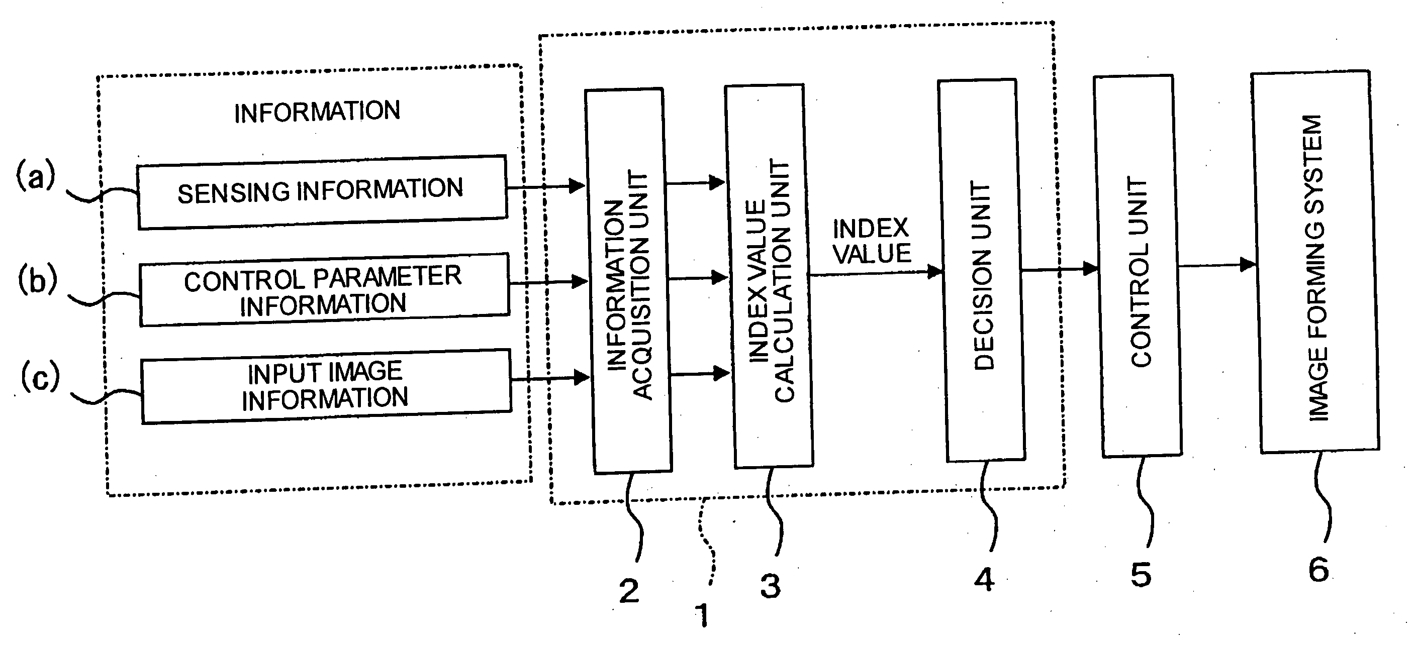
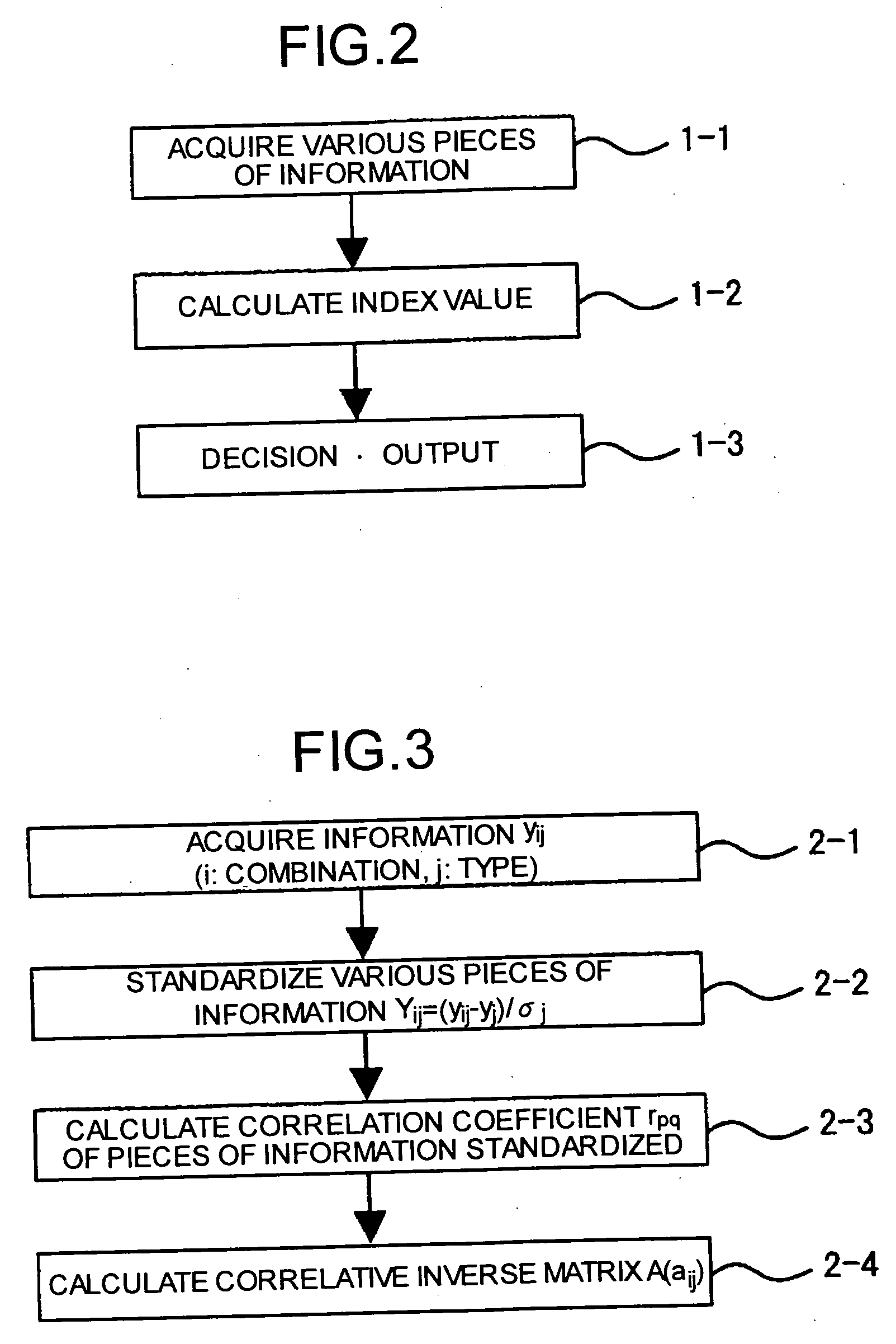
In a state deciding apparatus, an information acquiring unit acquires pieces of information of different types related to a state of an image forming apparatus. An index value calculating unit calculates an index value based on the pieces of information acquired. A state change deciding unit decides a change in a subsequent state of the image forming apparatus, based on a temporal change in the index value calculated.

Description

CROSS-REFERENCE TO RELATED APPLICATIONS The present document incorporates by reference the entire contents of Japanese priority document, 2003-184929 filed in Japan on Jun. 27, 2003. BACKGROUND OF THE INVENTION 1) Field of the Invention The present invention relates to an image forming system such as a copying machine, a printer, or a facsimile, an abnormal state occurrence predicting method in the image forming apparatus, and a state deciding apparatus that decides a state of the image forming apparatus. 2) Description of the Related Art In an image forming apparatus of an electronic photographing scheme, maintenance such as repair, and replacing consumable articles like toner and a photosensitive member needs to be performed. When a failure occurs, all or some of the functions of the apparatus must be stopped until repair is finished, and a user has to suffer a time loss. Therefore, if an occurrence of an abnormal state such as occurrence of a failure, or the need for replaci...

Claims


Application Information

Patent Timeline
Patent Type & Authority Applications(United States)
IPC IPC(8): B41J29/46G03G21/00B41J29/42G06F3/12G06F11/00
CPCG06F3/1204G06F11/008G06F3/1284G06F3/1259
Inventor SHOJI, HISASHIMIYAWAKI, KATSUAKISATOH, OSAMUYAMADA, MASAAKIHIRAI, SHUJINAKAGAWA, YOSHINORIOHTA, EIICHISETO, TAKASHIOUCHI, SATOSHIMATSUURA, NEKKA
Owner RICOH KK
Why Eureka
Try Eureka