Lens plate, method for manufacturing the same and image transfer device

a technology of lens plate and image transfer device, which is applied in the field of lens plate, can solve the problems of difficult to obtain the aspect ratio of the groove, the depth of the formable groove is limited, and the inability to remove the stray light made by the light obliquely entering the lens

Active Publication Date: 2005-01-06
NIPPON SHEET GLASS CO LTD
View PDF12 Cites 36 Cited by
  • Summary
  • Abstract
  • Description
  • Claims
  • Application Information

AI Technical Summary

Benefits of technology

[0019] And the erecting lens array is provided with a slit-shaped opening for removing unnecessary light beams within the object point side working distance and / or the image point side working distance.

Problems solved by technology

However, since an erecting unit magnification lens array using a conventional resin lens plate does not have a wall for shading a light beam between lenses adjacent to each other, there is a problem of stray light that a light beam obliquely entering a lens plate obliquely proceeds inside the plate, enter an adjacent convex lens and exits from the exit side of the lens to form a ghost image.
However, the formation of light shading layers around lenses, between adjacent lenses and between lens plates arranged opposite to each other is effective for removing the light coming in from the outside of a lens area or removing the light obliquely entering a lens and exiting from the outside of a lens area, but cannot remove the stray light made by the light obliquely entering a lens, passing through a lens plate in the direction of thickness and exiting from the exit side of a lens adjacent to that lens.
And in case of a method of forming a light shading layer by forming a groove and filling up the groove with a light absorbing paint, in a structure in which a light shading layer is formed by forming a groove by means of a transfer molding method using a metal mold and forming a light shading film on the side faces and bottom face of this groove, the depth of a formable groove is limited by the formability of a lens shape or the releasability of a lens plate from the metal mold.
Therefore, it is difficult to obtain a groove having an aspect ratio necessary for forming a light shading layer necessary for removing the stray light formed by the light obliquely entering a lens, passing through a lens plate in the direction of thickness and exiting from the exit side of a lens adjacent to that lens.
Therefore, an erecting unit magnification lens array using a conventional resin lens plate has still a problem that it cannot sufficiently remove stray light, makes a ghost image and is inferior in resolution.

Method used


Image

  • Lens plate, method for manufacturing the same and image transfer device
  • Lens plate, method for manufacturing the same and image transfer device
  • Lens plate, method for manufacturing the same and image transfer device

Examples


first embodiment

[0071] Next, the present invention is described with reference to the drawings.

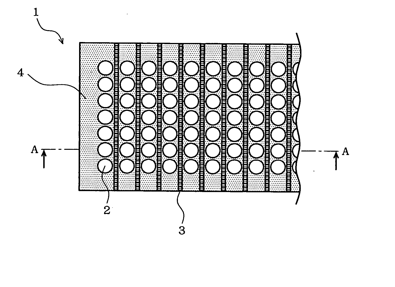
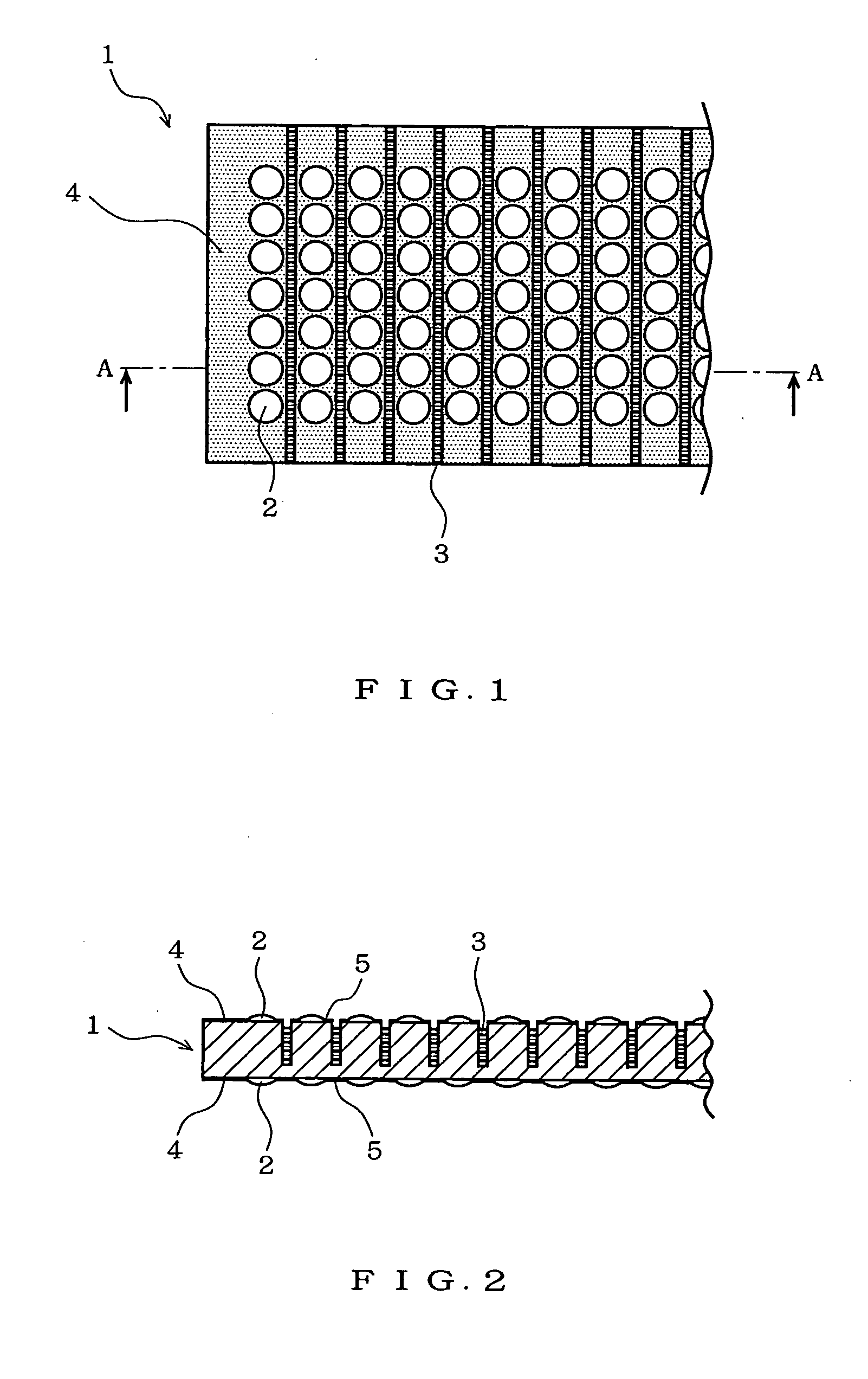
[0072]FIG. 1 is a plan view showing a lens plate for forming an erecting lens array to be used in a projector for projecting a three-dimensional or two-dimensional image in space, an image projector for projecting an image onto a screen and an image-transfer device for forming an image on a light receiving device or a photosensitive member, and FIG. 2 is a sectional view taken along line A-A of FIG. 1.

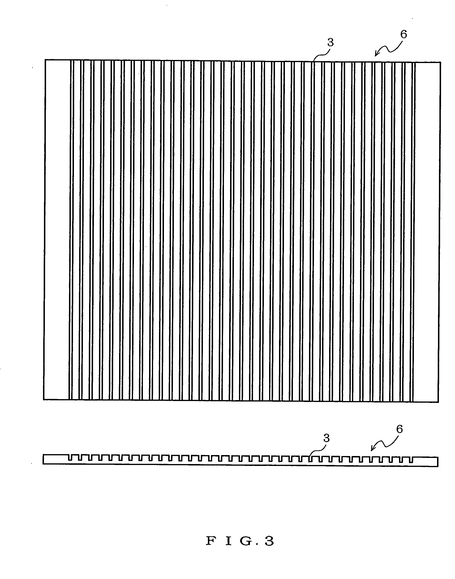
[0073] A lens plate 1 has a plurality of rectangular grooves formed at specified intervals in parallel with one another in the short-side direction of it. A rectangular groove 3 has a high aspect ratio in which the depth of its opening is larger in comparison with the width of it. In this case, a groove having a depth of about 4 times the width of its opening and about 60% of the thickness of the lens plate 1 is formed. The rectangular groove 3 is preferably formed to a depth of ⅓ or more of the thickness o...

second embodiment

[0103] Next, the present invention is described with reference to the drawings.

[0104]FIG. 13 is a plan view showing a lens plate for forming an erecting lens array to be used in an image transfer device for forming an image on a light receiving device or a photosensitive member, and FIG. 14 is a sectional view taken along line H-H of FIG. 13.

[0105] A material for a lens plate 21 is preferably a material being thermoplastic, high in light transmittance and low in moisture absorbency. In this embodiment, a lens plate of 2.29 mm in thickness is formed out of a cycloolefin-based resin by an injection molding process. A material for the lens plate 21 may be an acrylic-based resin.

[0106] Convex micro-lenses 22 each are a spherical lens of 0.35 mm in lens diameter and 0.66 mm in radius of curvature, are arranged in a hexagonal arrangement in which lenses are hexagonally arranged at intervals of 0.45 mm in lens pitch, and are formed on both faces of the lens plate 21 and the optical axes ...


PUM


Abstract

Spherical convex micro-lenses are arranged between rectangular grooves adjacent to each other of a lens plate. The arrangement of convex micro-lenses is made to be in parallel with the short-side direction of the lens plate, namely, the direction of the rectangular grooves. Since stray light appears mainly on the convex micro-lenses arranged in the long-side direction of the lens plate, the stray light to appear in the long-side direction of the lens plate is removed by forming grooves at regular intervals in the long-side direction of the lens plate and forming a light absorbing film in each of the rectangular grooves. Or the stray light to appear in the long-side direction of the lens plate is removed by making the direction of arrangement of convex micro-lenses different from the long-side direction of the lens plate.

Description

BACKGROUND OF THE INVENTION [0001] 1. Field of the Invention [0002] The present invention relates to a lens plate capable of removing stray light, a method for manufacturing the same and an image transfer device for transferring an image to a linear image formation area using an erecting lens array formed by combining the lens plates with one another. [0003] 2. Description of the Related Art [0004] As an optical system of a device for reading an image, there are a reducing system and a unit magnification system. A lens array to be used in a unit magnification system is an erecting unit magnification lens array and ordinarily has several rows of rod lenses arranged in the long-side direction of the lens array (in the main-scanning direction of an image reading device). Although it is possible to improve the transferability of light quantity and reduce the unevenness in quantity of transmitted light by increasing the number of rows of lenses, the number of lens rows is one or two in g...

Claims


Application Information

Patent Timeline
Patent Type & Authority Applications(United States)
IPC IPC(8): G02B3/00G02B5/22
CPCB29D11/00278G02B3/0031G02B5/005G02B3/0062G02B3/0068G02B3/0056G02B3/00G02B5/22
Inventor NEMOTO, HIROYUKISATO, SHIRO
Owner NIPPON SHEET GLASS CO LTD
Why Eureka
Try Eureka