

Toner and image forming method
a technology applied in the field of toner and image forming method, can solve the problems of easy scattering of toner, easy leakage of toner, and hardly obtained images with constant quality, and achieve excellent image stability, efficient and uniform frictional charging, and excellent image stability.
Inactive Publication Date: 2007-09-06
RICOH KK
View PDF58 Cites 101 Cited by
- Summary
- Abstract
- Description
- Claims
- Application Information
AI Technical Summary
Benefits of technology
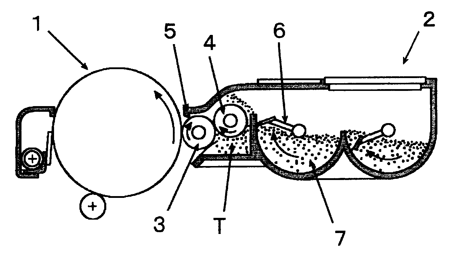
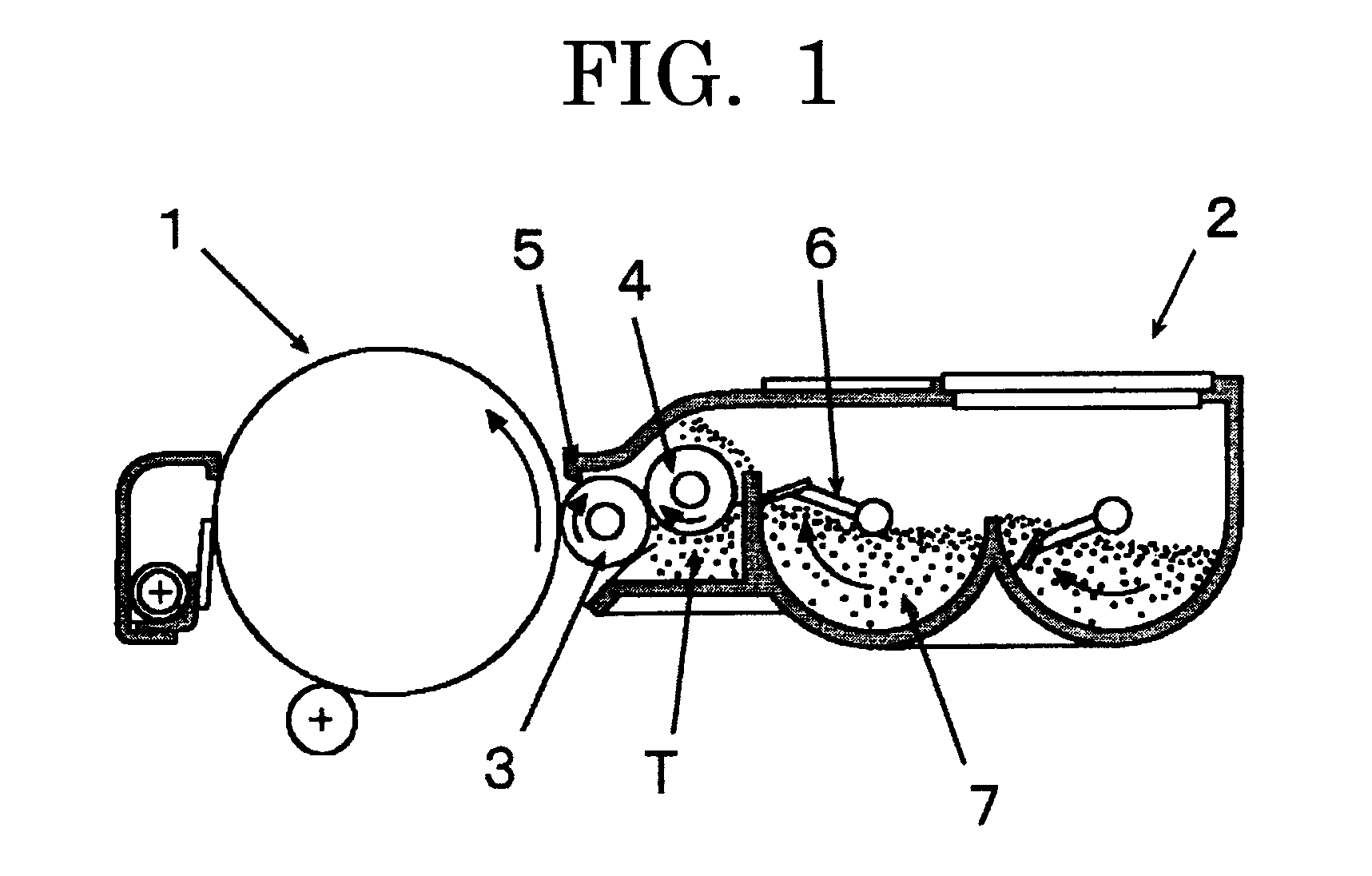
The present invention provides a solution for toner development issues in electrostatic charge development used for copy machines and printers. The invention uses a particular organic boron composition as a charge controlling agent and treats the toner with a particular inorganic particle. This results in excellent image stability by efficiently and uniformly performing frictional charging between the developing roller and a regulating blade in a developing device. The invention also includes a non-magnetic one-component image forming method that prevents scumming and leakage of toner caused by charge defects on the developing roller. The toner and the developing device have been designed to work together to achieve the desired results.
Problems solved by technology
In the former system, the good images are obtained relatively stably, but the images with constant quality are hardly obtained over a long time because the carrier is easily deteriorated and variation in a mixed ratio of the toner and the carrier occurs easily, and there are also drawbacks in maintenance and downsizing of the apparatus.
When the charge amount is low, a binding force to the developing roller becomes weak, spout from a developing device and recovery defect to the developing device occur, scattering of the toner and leakage of the toner easily occur.
In order to solve such problems, various treating agents are used as described later, but various problems occur.
In magnesium silicate minerals (attapulgite, sepiolite) described in Japanese Patent Application laid-Open (JP-A) No. 2002-31913, a percent of water content is high, charge defect easily occurs even in the ordinary use environment, and problems such as scumming, toner leakage, and toner scattering caused by the charge defect occur easily.
When magnesium silicate treated with silicone oil described in JP-A No. 03-294864, JP-A No. 04-214568 and JP-A No. 05-165257, due to the silicone oil, fluidity of the toner is deteriorated and charge increase is caused, feeding defect and density reduction are caused in the developing device.
Particularly in the toner using an organic boron compound, the durability is remarkably deteriorated and the image is harmfully affected.
In the toner described in JP-A No. 11-95480, when the toner is made by using magnesium silicate as a silicate fine powder body and making a coated rate 60% to 100%, if used as a negatively charged toner, a reversely charged toner occurs easily and the scumming is easily caused.
As the toner described in JP-A No. 11-184239, when a titanic acid fine powder body is used, this material itself is low resistant, thus, the leakage of charge is large, the scumming, the toner leakage and the toner scattering occur easily.
Thus, it is difficult to control an amount to be added, when added in a large amount, the charge leakage is large and the charge reduction of the entire toner is caused. when added in a small amount, the charge increase is caused.
Thus, in both cases, the scumming, the toner leakage and the toner scattering occur easily.
Method used
View moreImage
Smart ImageViewing Examples

Examples
example 1
[0138]To 100 parts by mass of the colored resin particles obtained as the above, 1 part by mass of the forsterite 1 (first inorganic fine particle) and 1 part by mass of silica RX200 (supplied from Japan Aerosil Co., Ltd., primary particle diameter: 12 nm, HMDS surface treatment) were added, and mixed using the Henschel mixer (at a peripheral velocity of 40 m / s for 60 seconds) to make the cyan toner 1.
[0139]The results of evaluating the toners obtained are shown in Table 1.
Login to View More PUM
 Abstract
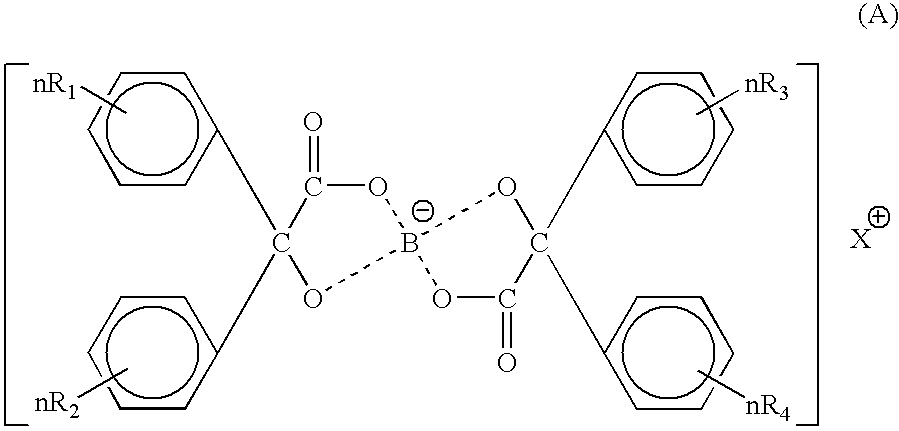
Toner for electrostatic charge development wherein no scumming occurs, and toner leakage caused by charge defect of the toner on a developing roller can be inhibited, and an excellent image stability is obtained is provided.The toner used for an image forming method having a latent electrostatic image forming step of forming a latent electrostatic image on a latent electrostatic image bearing member primarily charged, a developing step of developing the latent electrostatic image by each toner which multiple developing devices have to form a toner image on the latent electrostatic image bearing member, a transferring step of transferring the toner image with respective colors formed on the latent electrostatic image bearing member onto a recording material and a fixing step of fixing the toner image transferred onto the recording material, wherein the toner comprises a colorant and a resin and contains an organic boron compound represented by a following chemical formula (A) as a charge controlling agent, further the toner is treated with an inorganic fine particle and at least one of the inorganic particles is a magnesium silicate compound represented by a following general formula [2] is provided.wherein X is an alkali metal, R1, R2, R3 or R4 each represents a hydrogen atom, an alkyl group having 1 to 4 carbon atoms, an alkoxy group having 1 to 4 carbon atoms, or a halogen atom.MgxSiyO(x+2y) [2]wherein x and y are integers.
Description
BACKGROUND OF THE INVENTION[0001]1. Field of the Invention[0002]The present invention relates to toner for electrostatic charge development used for copy machines and printers practically applying electrographic technology, and an image forming method using the same.[0003]2. Description of the Related Art[0004]In conventional electrographic methods, a latent electrostatic image formed by charging and exposing a photoconductor surface is developed by colored toners to form a toner image, the toner image is transferred onto a member to be transferred such as transfer paper and this is fixed with a heat roll to form an image.[0005]In a dry development system employed in the electrographs and electrostatic recordings, a system using a two-component developer composed of the toner and a carrier and a system using a one-component developer containing no carrier are available. In the former system, the good images are obtained relatively stably, but the images with constant quality are har...
Claims
Login to View More Application Information
Patent Timeline
 Patent Type & AuthorityApplications(United States)
IPC IPC(8): G03G9/08
CPCG03G9/09708G03G9/09783G03G9/09725
InventorKADOTA, TAKUYAHAGI, MASAYUKIMIKURIYA, YOSHIHIROKUROSE, KATSUNORIKATO, HIROAKIYAMAMOTO, ATSUSHIISHIKAWA, YOSHIMICHIINOUE, MASAHIDENAKAMURA, MINORUYASUNAGA, HIDEAKI
OwnerRICOH KK