

Lateral and uplift resistance apparatus and methods for use in structural framing
a technology of structural framing and uplift resistance, which is applied in the direction of girders, building repairs, walls, etc., can solve the problems of uneven walls, difficult strip tightness, and inability to allow field modification
- Summary
- Abstract
- Description
- Claims
- Application Information
AI Technical Summary
Problems solved by technology
Method used
Image

Examples
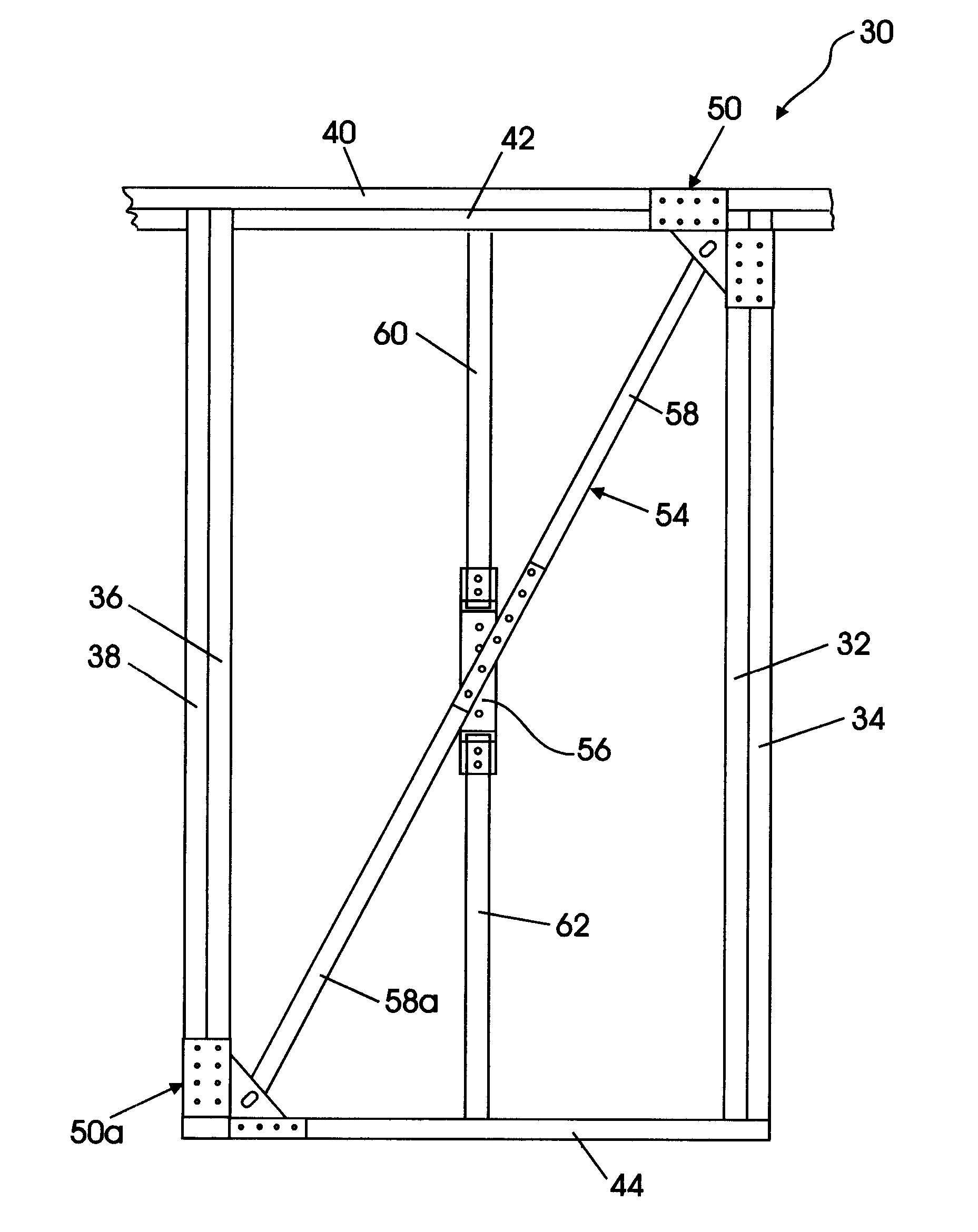
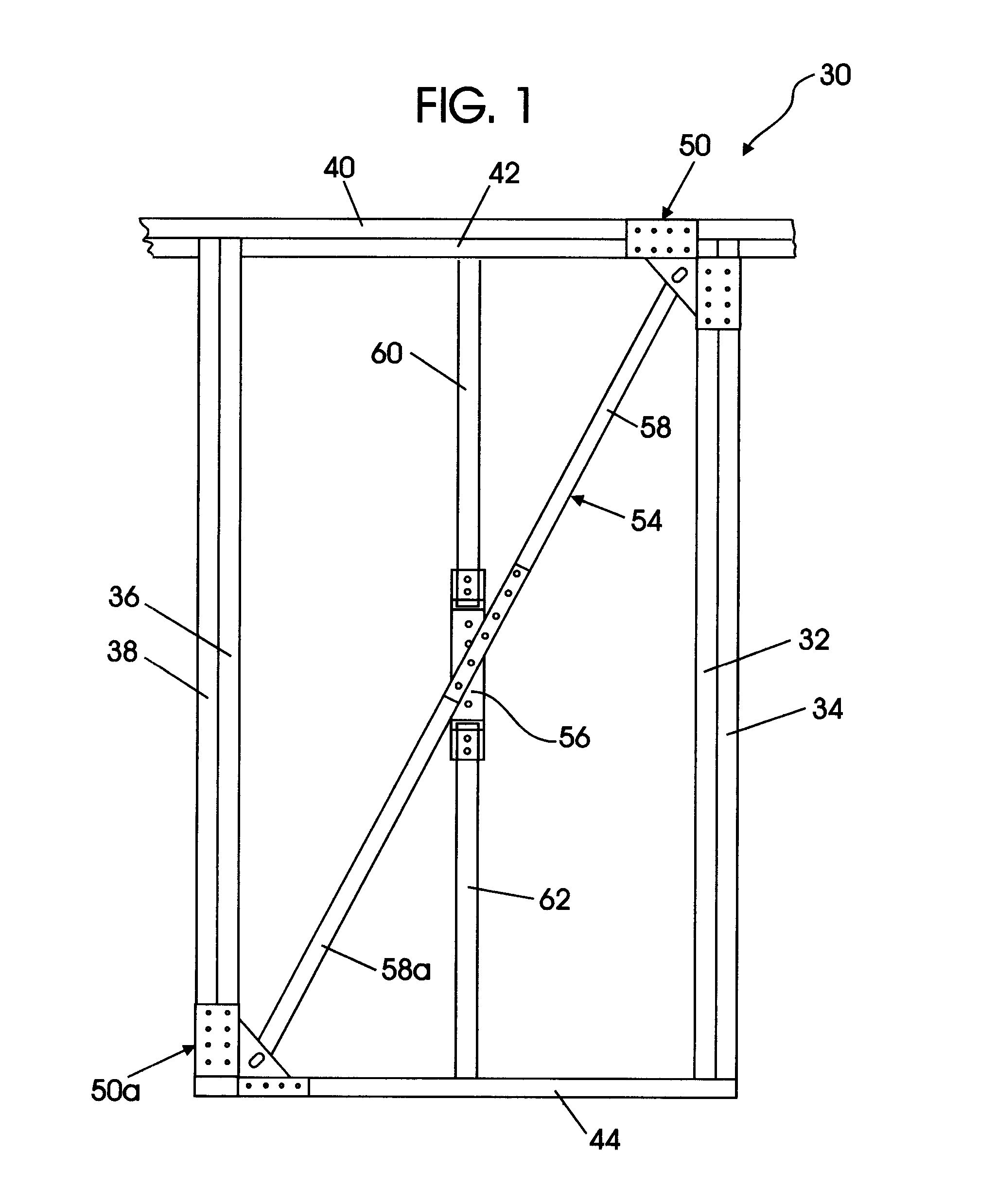
embodiment 30
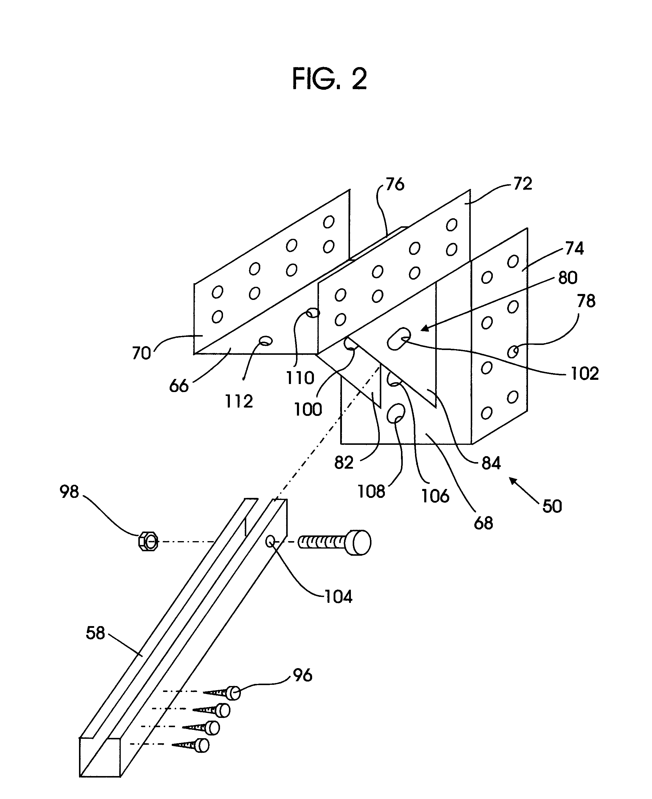
[0048]FIG. 3 shows an exploded view of an embodiment 30 of the present invention. The sill clip 50a is fabricated similarly to the head clip 50. In addition, one embodiment includes anchors 90 through the sill clip 50a, such as chemical or wedge anchors, to be placed into a concrete foundation. Such anchors 90 axially resist uplift forces.
[0049] The tension strut 54 has an adjustable length based on sliding, or telescoping, the web members 58, 58a and then fastening them using fasteners 96. Fastening of the web members 58, 58a to each other and to the triangular bracket members 82, 84 may be done with, for example, self-tapping screws, pre-drilled holes with screws or bolts as shown, or welding. As shown in FIG. 2, the upper end of the tension strut 58 is mounted to the bracket 80 of the head clip 50 by a bolt 98 that passes through holes 100, 102 in the triangular bracket members 82, 84 and through a hole 104 in the tension strut 54. The holes 100, 102 may be, for example, round, o...
embodiment 50
[0050] The head clip 50 is shown in the side view embodiment 50 of FIG. 4 have a slotted hole 102 through bracket member 84 for attaching the tension strut 54 to the head clip 50. A corresponding opening, slotted hole 100, penetrates the other bracket member 82 (FIG. 3). A slot 100, 102 may be used instead of a round hole in order to avoid compression force on the tension strut 54. As shown in the head clip 50 and sill clip 50a embodiments of FIGS. 4 and 7, when installed the tension strut 54 should be as short as possible, with the bolts 98, 98a on the edges of the slots 100, 100a and slots 102, 102a that are proximate to each other. When using this tension strut 54, it is necessary to ensure that the structure itself is “tight.” Connections should be made in a manner to assure that they will be initially free of slack and will not loosen under load reversals or repeated loading. This means avoiding connections that are loose or that allow movement between the structural members. A...
PUM
 Abstract
Description
Claims
Application Information