
Single proof mass, 3 axis MEMS transducer

Active Publication Date: 2005-01-13
NORTH STAR INNOVATIONS
View PDF11 Cites 94 Cited by
  • Summary
  • Abstract
  • Description
  • Claims
  • Application Information

AI Technical Summary

Benefits of technology

[0012] In one aspect, a transducer is provided which comprises an unbalanced proof mass, and which is adapted to sense acceleration in at least two, and preferably three, mutually orthogonal directions. The transducer preferably contains a single proof mass that is mounted to the substrate on a suspension that is compliant in all three axes, and two or more conductive plates that are mounted on the substrate under the proof mass. The proof mass preferably comprises a first set of sense fingers aligned along a first axis, and a second set of sense fingers aligned along a second axis, wherein said first and second axes are orthogonal. Each of the sense fingers in the first and second set is typically surrounded by two parallel fingers that are fixably attached to a substrate. The first and second set of sense fingers are preferably disposed in an arrangement that has at least two planes of symmetry, and more preferably, at least four planes of symmetry. It is also preferred that the conductive

Problems solved by technology

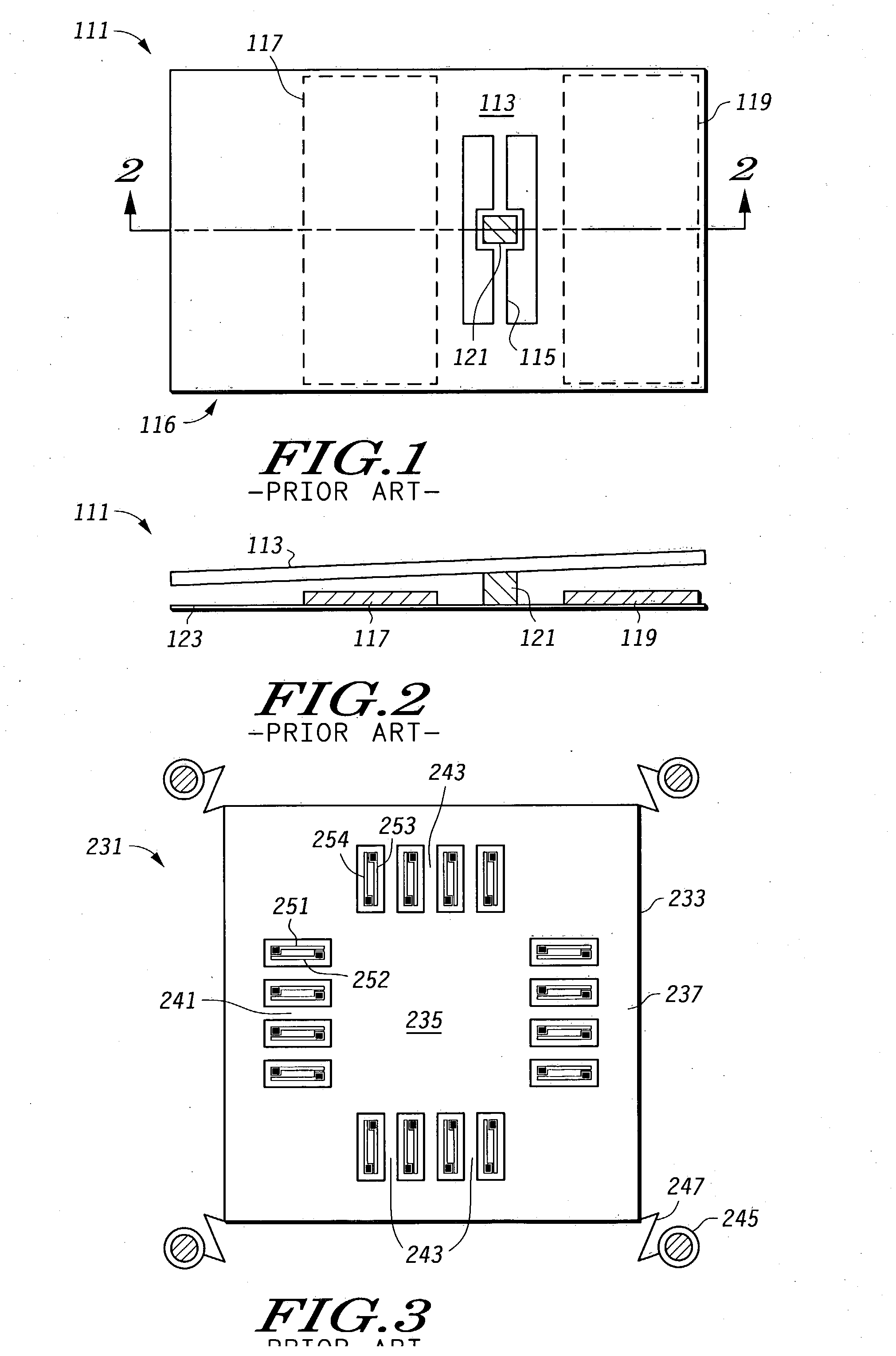
The use of an unbalanced proof mass in this device is required, because a balanced proof mass would not tilt when subjected to Z axis acceleration, and hence would not properly sense the acceleration.
However, the final package resulting from such a configuration is inherently bulky, since each accelerometer must be positioned such that its sense axis is orthogonal to the sense axes of the other accelerometers.
Hence, the entire package can never be formed as a single planar device.
Compared to a two layer process flow, a three layer process flow is less desirable in that it requires at least two additional masking steps.
Consequently, devices manufactured by a three layer process are generally more expensive to manufacture, and have a lower yield, than comparable devices manufactured via a two layer process.
Transducers made by a three layer process flow are also typically more susceptible to packaging stresses and conductive layer stress gradients than those made by two layer process flows.
These effects are particularly problematic for the Z axis output of the device.
However, such coatings complicate the manufacturing process.

Method used


Image

  • Single proof mass, 3 axis MEMS transducer
  • Single proof mass, 3 axis MEMS transducer
  • Single proof mass, 3 axis MEMS transducer

Examples


Embodiment Construction

[0027] The terms “two layer” and “three layer”, when used herein in reference to an accelerometer or transducer or to a process flow for making the same, refer to the number of layers of conductive material (typically doped polysilicon) used to fabricate the sense capacitor plates present in the device or required by the manufacturing process.

[0028] In accordance with the teachings herein, a compact, single die transducer, which may be, for example, an accelerometer or other sensing device, is provided which may be fabricated in a two layer process flow. Embodiments made from a two layer process flow may be easier and less expensive to implement than a typical three layer process flow. Moreover, the resulting transducer has no contribution to package stress sensitivity from the third conductive layer. The transducer can be made to sense along two or more mutually orthogonal axes.

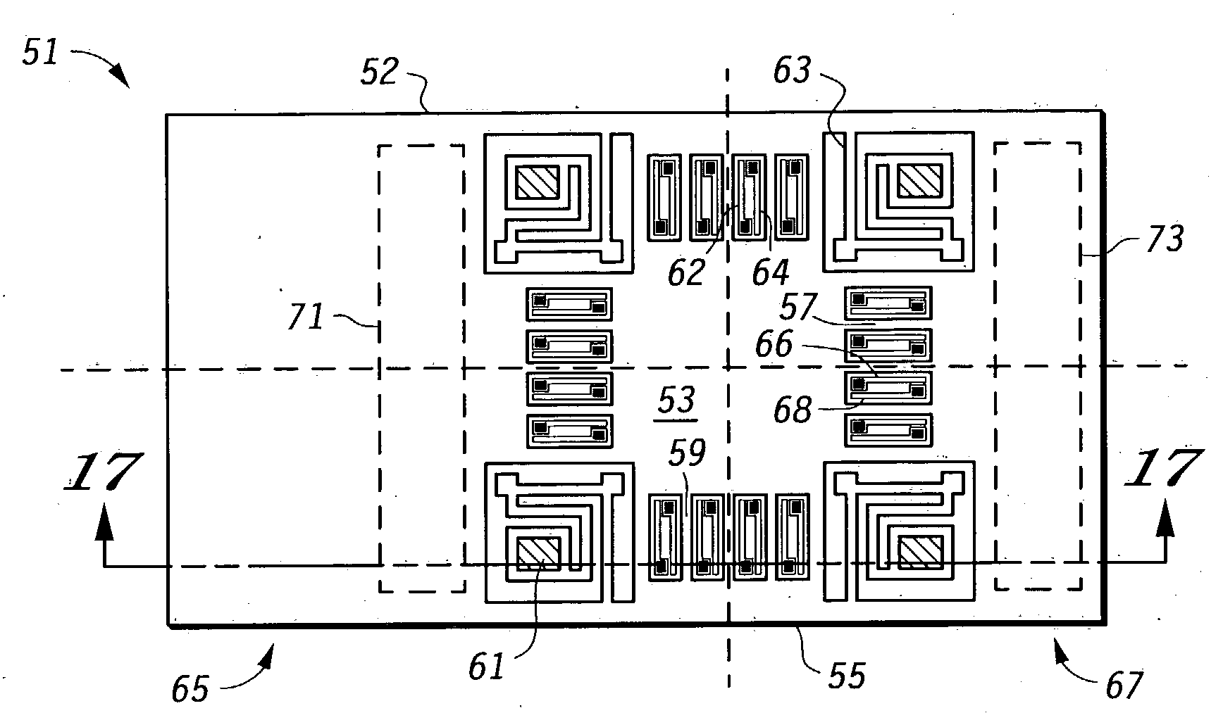
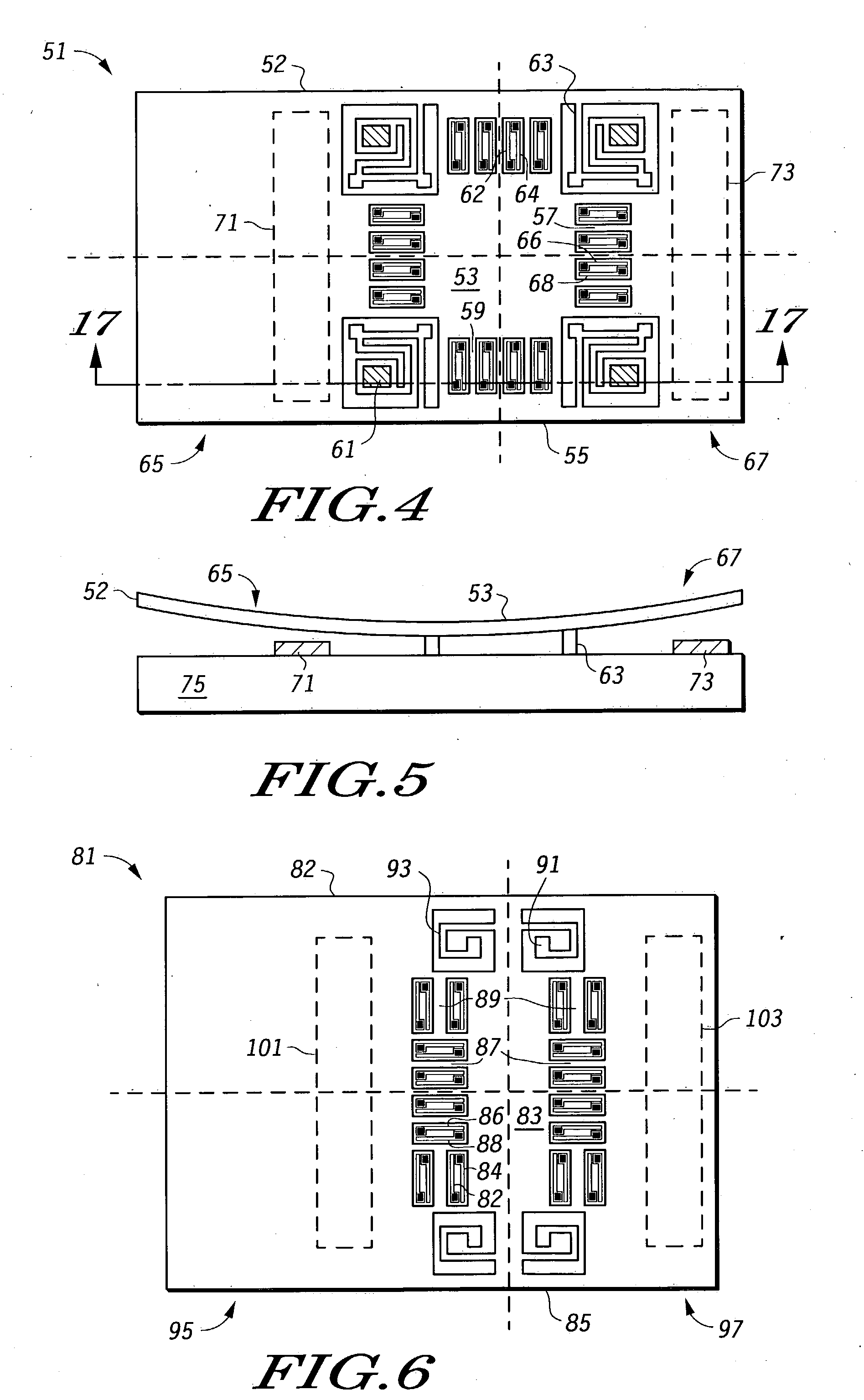
[0029]FIGS. 4-5 depict one embodiment of a transducer 51 made in accordance with the teachings herein. ...


PUM


Abstract

A transducer is provided herein which comprises an unbalanced proof mass (51), and which is adapted to sense acceleration in at least two mutually orthogonal directions. The proof mass (51) has first (65) and second (67) opposing sides that are of unequal mass.

Description

FIELD OF THE INVENTION [0001] The present invention relates generally to microelectromechanical sensors (MEMS), and more particularly to transducers containing proof masses. BACKGROUND OF THE INVENTION [0002] Transducers are useful in inertial guidance systems to sense the acceleration or orientation of a device, such as a spacecraft, aircraft, land-based vehicle, or handheld device. They are also used in vehicles to sense impacts and deploy various devices to protect the passengers (for example, air bags in automobiles). Transducers may be required to sense acceleration or other phenomena along one, two, or three axes or directions. From this information, the movement or orientation of the device can be ascertained. [0003] In the ongoing effort to reduce the size and cost of transducers, a variety of sensing devices have been proposed. Many of these devices, especially those which function as accelerometers, include capacitive structures, some of which are constructed using semicon...

Claims


Application Information

Patent Timeline
IPC IPC(8): G01P15/125G01P15/18
CPCG01P15/18G01P15/125G01P2015/082G01P2015/0831
Inventor MCNEIL, ANDREW C.LI, GARYKOURY, DANIEL N. JR.
Owner NORTH STAR INNOVATIONS
Learn More