Container and pusiier

a technology of containers and pusiiers, applied in the field of containers, can solve the problems of high manufacturing cost and high cost of container disposal, and achieve the effects of reducing manufacturing costs, eliminating the inability to spout, and reducing the cost of disposal

Inactive Publication Date: 2005-01-13
SHARP KAGAKU INDS
View PDF12 Cites 26 Cited by
  • Summary
  • Abstract
  • Description
  • Claims
  • Application Information

AI Technical Summary

Benefits of technology

[0015] In the present invention, in place of the conventional cartridge having a movable bottom placed inside a rigid cylinder body, a sealant is housed in a pouch having flexibility as a whole, and the structure of the spout formed at one end of the pouch is fixed to the extruder, or the unstableness of the spout formed at one end of the pouch is controlled by the adjusting member placed on the extruder; thus, it becomes possible to achieve the aforementioned objective of the invention.
[0016] In other words, in the container of the present invention, a liquid such as a sealant is housed in a flexible container such as a pouch prepared by forming a film-shaped material into a bag shape with a spout being attached to one end thereof, and a flange portion formed on an extrusion nozzle that forms the spout and a flange portion formed on a spout base member are allowed to sandwich the vicinity of a through hole that is used for allowing the spout to face outside, and this state is fixed through a screw engagement. The through hole may be conventionally formed in one end face of the main body of an extruder of a closed type. Thus, although the pouch serving as the container main body is a flexible member, the unstableness of the spout is eliminated even when the spout is made in contact with an application face upon applying the sealant or the like so that the viscous liquid such as the sealant that is the content can be extruded by a required amount each time under the same workability as the conventional cartridge. Further, it has been confirmed through experiments that the content can be virtually extruded without any remaining portion. Since the main body of the container of the present invention is prepared as the flexible pouch, the size of the container after the extrusion of the content is greatly reduced in comparison with the conventional rigid cartridge, and the costs required for the disposal thereof are also greatly reduced; thus, it becomes possible to greatly reduce the manufacturing costs thereof.
[0017] The container of the present invention in accordance with invention 2 is constituted by the above-mentioned pouch, a spout base member that is bonded to one end thereof and an extrusion nozzle that is engaged by this spout base member. This extrusion nozzle is allowed to face outside through a hole that is used for exposing the spout formed on one end face of a cylinder-shaped main body of the extruder of a conventional closed type. A flange portion is formed on the base end portion of the extrusion nozzle so as to be freely de

Problems solved by technology

The conventional cartridge as described above has a problem in that the volume thereof is unchanged even after the content has been consumed to cause high costs required for disposal of the container in compliance with the containers and packaging r

Method used


Image

  • Container and pusiier
  • Container and pusiier
  • Container and pusiier

Examples


Embodiment Construction

[0022] (Embodiments of the Present Invention)

[0023] Referring to Figures, the following description will discuss embodiments of the present invention.

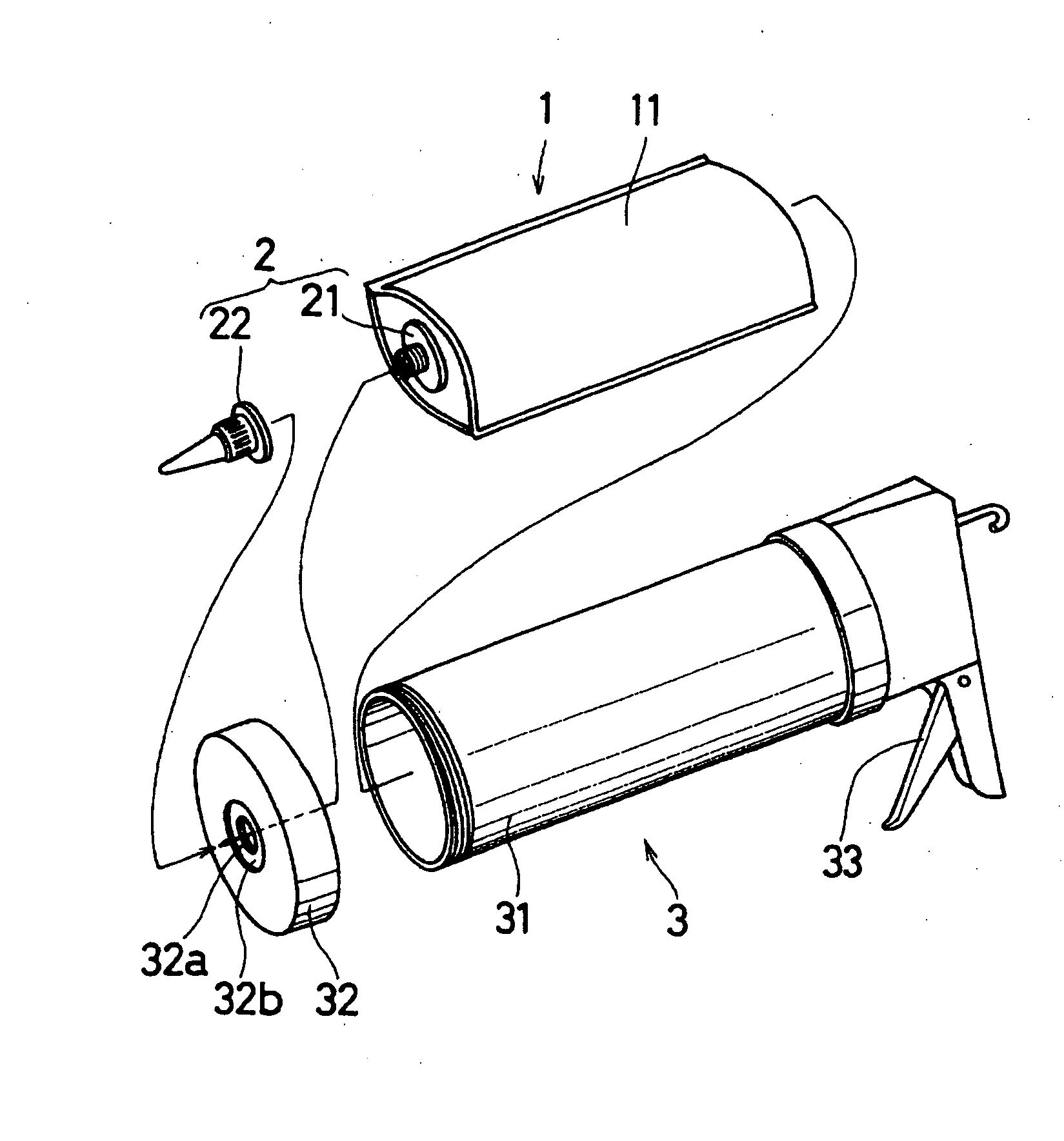
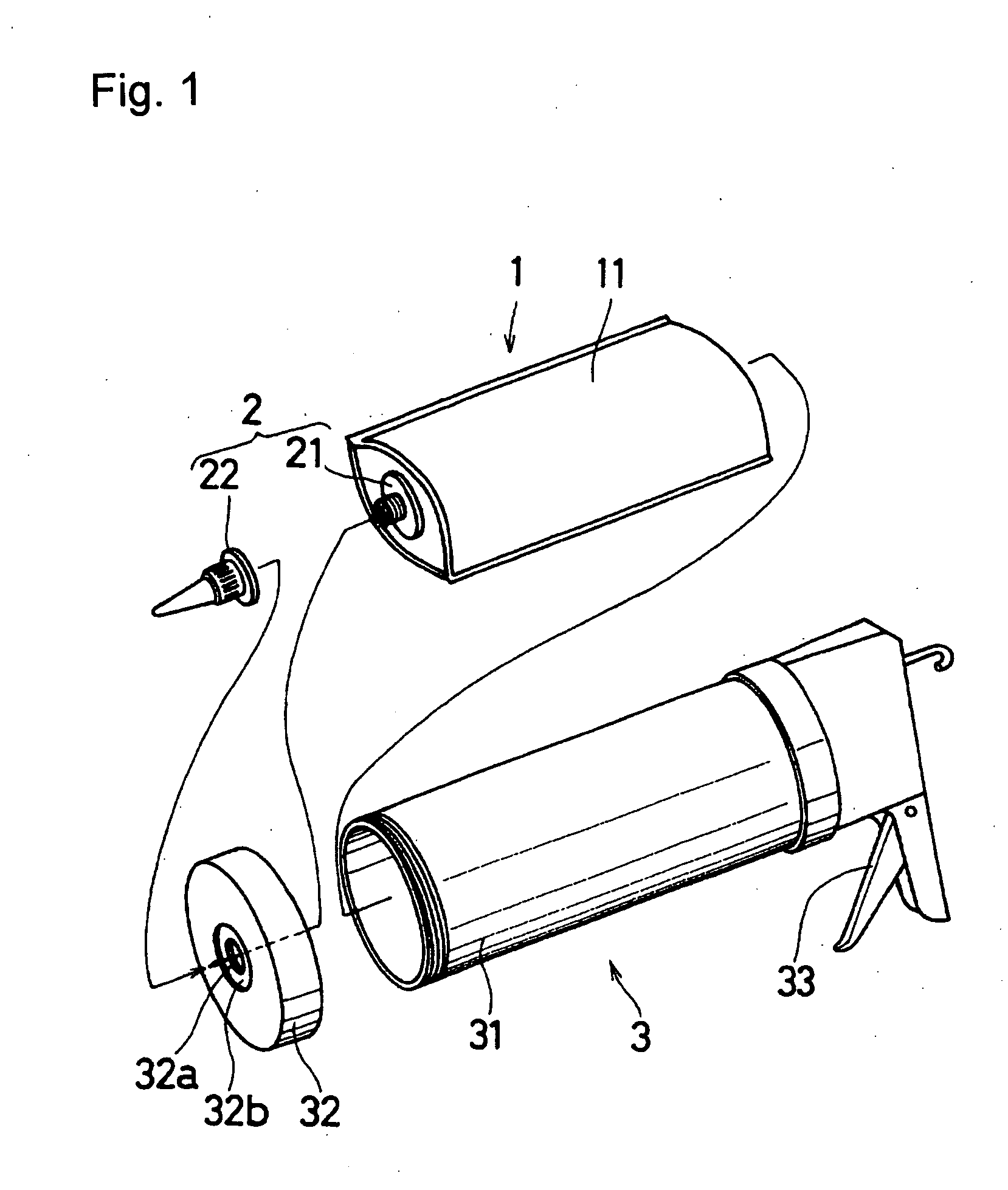
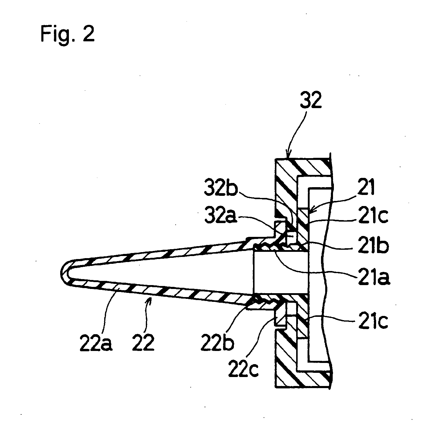
[0024]FIG. 1 is an explanatory drawing of an embodiment of a container of the present invention, which is a perspective view that shows a state when inserted in an extruder. FIG. 2 is a cross-sectional view that shows the vicinity of the spout when the container of the present invention is inserted to the extruder.

[0025] As shown in FIG. 1, a pouch 11 is a bag having a ship-bottom shape, and is made from a film material, so that it is flexible. A liquid such as a sealant and an adhesive is sealed in the pouch 11. The film material to be used here needs to prevent invasion of various gases so as to prevent the sealed content from curing and deteriorating. For this reason, a composite material formed by laminating films of several kinds is used.

[0026] In the case when, for example, the content is a silicone-based sealant that reacts ...


PUM


Abstract

A container, which houses a liquid such as a sealant in a flexible pouch 11 in a sealed state, is provided with a spout 2 that is constituted by an extrusion nozzle 22 and a spout base member 21 and formed on one end thereof so that the extrusion nozzle 22 is fixed by sandwiching the vicinity of a hole 32a formed on one end face of an extruder 3 by a flange portion 21c of the spout base member 21 and a flange portion 22c of the extrusion nozzle 22, and an extruder 3a is arranged so that an adjusting member 322b, which controls the tilt of the nozzle 22, is allowed to protrude outward from a hole 322a of the extruder 3a.

Description

TECHNICAL FIELD [0001] The present invention relates to a container for housing a liquid such as an adhesive, for example, typically represented by a sealant, and also concerns an extruder that is suitably used for housing such a container and for extruding the content to a predetermined place by a predetermined amount each time. BACKGROUND ART [0002] In general, adhesives typically represented by sealants such as silicon sealants have been introduced to the market in a housed state in a cartridge 4 made of an injection molded body of a resin, as shown in FIG. 13 in its cross-section, and upon application, the adhesive is used while being extruded by a predetermined amount each time, by using an extruder 3 that is referred to as a coking gun and commercially available, as shown in FIG. 14(A) in its external view and FIG. 14(B) in its cross-sectional view of the essential portion. [0003] The cartridge 4 has a structure in which a cylinder-shaped outlet 42 is attached to one end of a ...

Claims


Application Information

Patent Timeline
IPC IPC(8): B05C17/005B05C17/01B65D33/36B65D35/30B65D83/00
CPCB05C17/00513B05C17/00516B65D83/0005B05C17/01B05C17/00583B05C17/00596
Inventor MIYATA, TANEOHASUI, YASUSHIMURAKAMI, MIKIOFUJIWARA, HIROFUMI
Owner SHARP KAGAKU INDS
Why Eureka
Try Eureka