Method, apparatus and program for compositing images, and method, apparatus and program for rendering three-dimensional model

a technology of compositing images and programs, applied in the field of compositing images, can solve the problems of cg image, nonlinear distortion of image taken by camera lens systems, and inability to produce incident light,

Inactive Publication Date: 2005-01-13
HONDA MOTOR CO LTD
View PDF7 Cites 18 Cited by
  • Summary
  • Abstract
  • Description
  • Claims
  • Application Information

AI Technical Summary

Benefits of technology

To obtain the ‘colors’ of each projection pixel, a consideration may preferably be given to the attributes of the corresponding portions of the 3D model, which attributes may include color (hue, brightness, saturation, etc.), reflectance, transparency, distance from the viewpoint, and the like.
According to the methods for compositing images as defined above, a good agreement is achieved in optics between a picture taken from life by a camera in the real world and a 2D computer-graphics image created from a 3D model in a virtual space on a computer. Consequently, the resultant composite image can be rendered natural, so that a moving video picture made from such composite images can be free from awkward or artificial impression.
According to the apparatuses for compositing images as defined above, when the 2D image generation unit determines the colors (attributes) of the projection pixels from the relationship between the lines of sight for tracing and the 3D model, a 2D image having the same optical properties as of the picture taken from life by the camera in the real world can be generated from the 3D model. Consequently, the composite image generated in the composite image generation unit can be rendered natural, so that a moving video picture made from such composite images can be free from awkward or artificial impression.

Problems solved by technology

In contrast, the real-world camera having lens systems, unlike the pinhole camera, is not adapted to produce rays of incident light to one point of convergence.
Thus, an image taken by the camera having lens systems contains nonlinear distortion, which is greater in peripheral areas.
Such displacements, if brought into a still image or frozen frame, possibly could not appear so obtrusive as to annoy a viewing person, but if brought into each image (frame) of a moving video picture, would slightly shake the CG image, producing an unnatural impression.
In a case where the camera pans to record a scene, the CG image of gauges, etc. would disadvantageously shake relative to the instrument panel during the scene in a sequence of the resultant composite images made by the aforementioned conventional method, though the CG image should move together with the instrument panel, without changing the relative positions thereof.

Method used


Image

  • Method, apparatus and program for compositing images, and method, apparatus and program for rendering three-dimensional model
  • Method, apparatus and program for compositing images, and method, apparatus and program for rendering three-dimensional model
  • Method, apparatus and program for compositing images, and method, apparatus and program for rendering three-dimensional model

Examples


Embodiment Construction

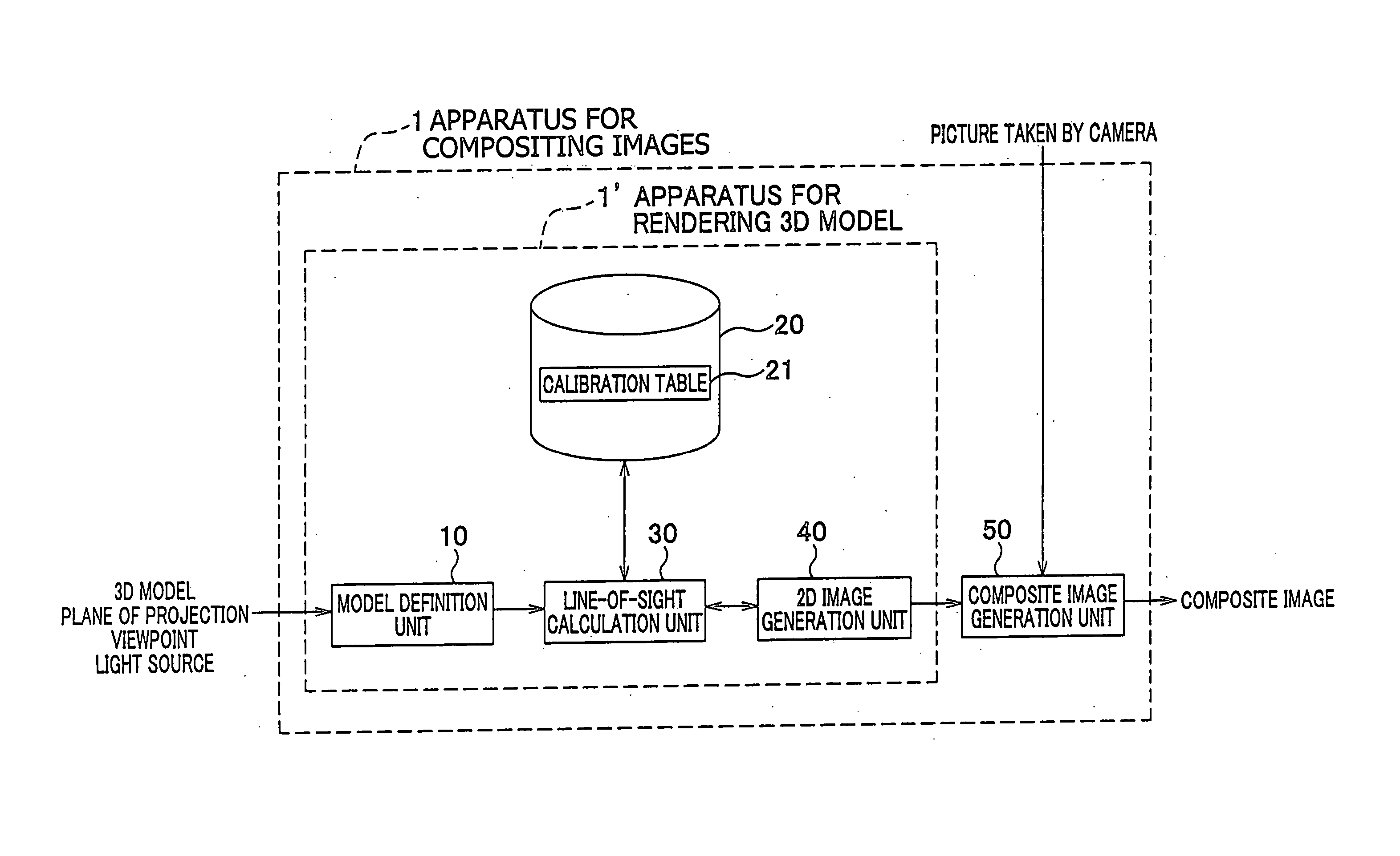
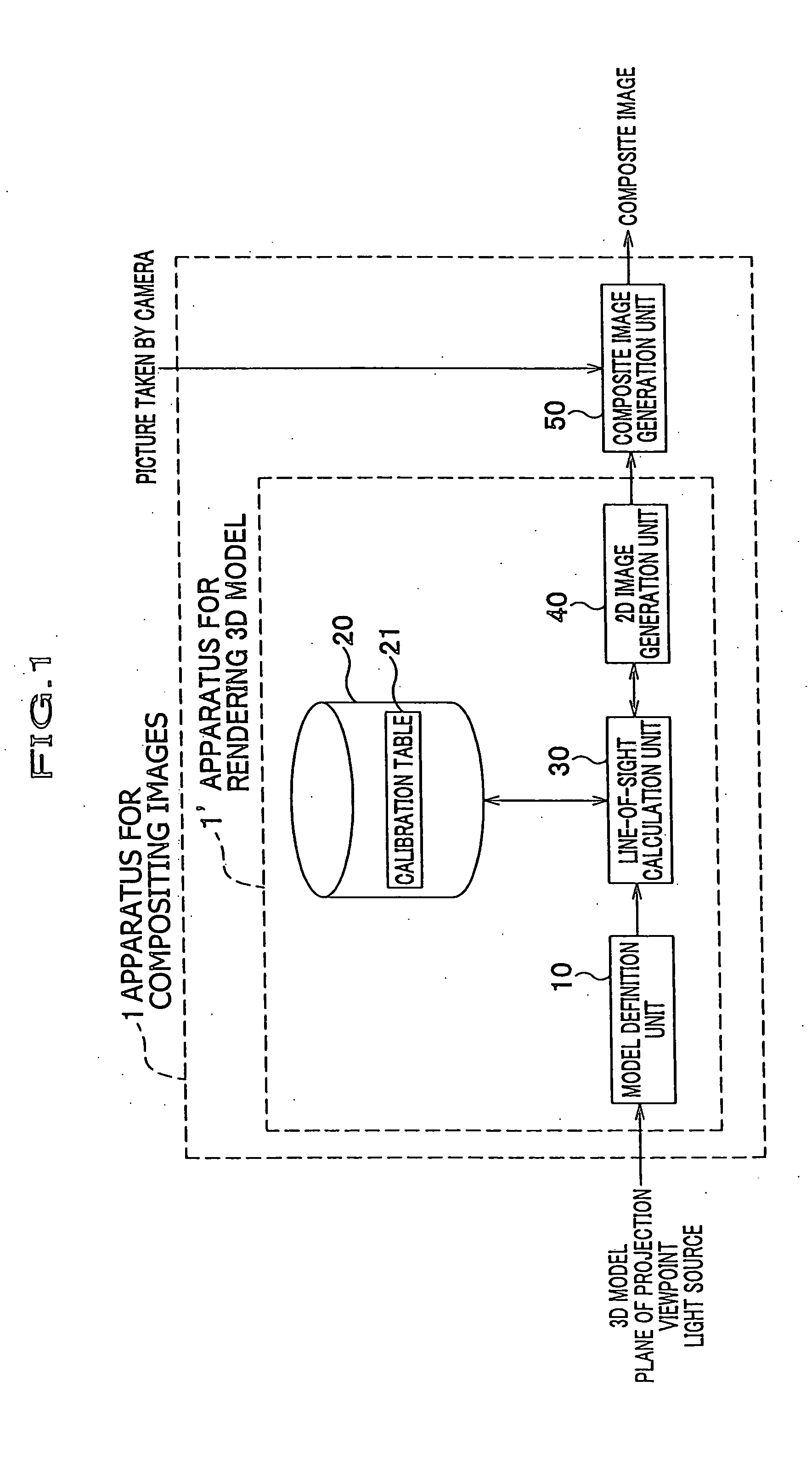
A detailed description of exemplified embodiments of the present invention will be given with reference to the drawings. First, the optical property of the real-world (“non-pinhole”) camera will be described in which rays of incident light does not travel through a single point and thus such distortion in images as could appear in the pinhole camera is eliminated. Next described is calibration data that represents the optical property of the non-pinhole camera in numerical form. Subsequent descriptions will give an idea of a calibration table which includes such calibration data, and illustrate a method of acquiring the calibration data for each pixel of an image taken by a camera to generate the calibration table. Further, a description will be given of apparatuses for compositing images and for rendering an image, which utilizes the calibration table, as exemplary embodiments of the present invention.

[Optical Property of Non-Pinhole Camera]

Referring now to FIG. 7, the mechanism ...


PUM


Abstract

A three-dimensional (3D) model OB, a plane of projection PL, a light source L and a reference viewpoint O are defined in a virtual space on a computer. When a line of sight LC for tracing from the reference viewpoint O to the 3D model OB and to the light source L is determined, the view point is corrected to be shifted from the reference viewpoint O by a displacement VD for each projection pixel PP, to obtain a proper line of sight LC. Accordingly, a computer-graphics image as thus rendered can be provided to be composited with a picture taken from life by a camera, thereby generating a composite image having a natural impression.

Description

BACKGROUND OF THE INVENTION This invention relates to a method, apparatus and program for compositing images, particularly a computer-graphic image and a picture taken by a camera, and a method, apparatus and program for rendering a three-dimensional model created by computer graphics into a two-dimensional image to be superposed on a picture taken by a camera to form a composite image. Two-dimensional representation (for on-screen presentation or the like) of a three-dimensional object modeled utilizing a computer (hereinafter referred to as “3D model”) is created by a “rendering” process. Among conventional methods for rendering a 3D model (i.e., generating a two-dimensional image therefrom) is ray tracing, which is disclosed for example in Japanese Laid-Open Patent Application, Publication No. 2000-207576 A. The ray tracing is, as shown in FIG. 5, a method in which a 3D model 101 created in a virtual space on a computer is converted into a two-dimensional image assuming that th...

Claims


Application Information

Patent Timeline
Patent Type & Authority Applications(United States)
IPC IPC(8): G06T15/06G06T15/80G06T19/00G09G5/00H04N5/272
CPCG06T19/006C02F3/109C02F3/106C02F2003/001
Inventor AOYAMA, CHIAKI
Owner HONDA MOTOR CO LTD
Why Eureka
Try Eureka