Carbon foam composite tooling and methods for using the same

a technology of carbon foam and composite materials, applied in the field of composite tooling, can solve the problems of not meeting the requirements, reducing the production efficiency of composite materials, so as to achieve the effect of less cost of production and/or use, easy modification, and more durabl

Inactive Publication Date: 2005-01-13
TOUCHSTONE RES LAB
View PDF36 Cites 30 Cited by
  • Summary
  • Abstract
  • Description
  • Claims
  • Application Information

AI Technical Summary

Benefits of technology

[0017] The disclosed tools may be lighter, more durable, and less costly to produce and / or use than conventional tools used for the production of composite parts, particularly those tools used for the production of CFC. Additionally, such tools may be reusable, repairable, and more readily modifiable than those tools of the prior art.

Problems solved by technology

Furthermore, composite forming materials, particularly carbon fiber, are relatively expensive and wastage is generally discouraged.
In fact, composites, particularly carbon fiber composites used in aerospace and many other applications, are routinely produced, within very restrictive tolerances, to the required size.
Conversely, if the CTE of the composite part is significantly greater than that exhibited by the tool face, the part may again be retained in the tool or may damage the tool face during contraction or cured composite dimensions may differ from those of the tool face.
Therefore it is very difficult to match the CTE exhibited by the tool face with the CTE of a carbon composite as there are few materials available for construction of the tool body that have sufficiently low CTEs.
However, INVAR® based tools are typically heavy, difficult to fabricate, and can require, for example, as many as seventeen separate stages to fabricate.
However, CFC based tools are usually susceptible to damage if not handled with care, especially when composite is laid thereon.
Additionally, surface degradation of CFC based tools may occur as a result of the repetition of the process cycle due to a combination of component adhesion, CTE mismatch, and oxidative decomposition.
Furthermore, any necessary repairs of CFC based tools leads to an increase in repair and maintenance costs.
Also, CFC based tools are subject to dimensional stresses from uneven support.
Accordingly, due to the aforementioned problems, CFC based tooling is not commonly used.
These cells typically approximate spheres or ovoids of regular, but not necessarily uniform, size, shape, distribution, and orientation.

Method used


Image

  • Carbon foam composite tooling and methods for using the same
  • Carbon foam composite tooling and methods for using the same
  • Carbon foam composite tooling and methods for using the same

Examples


Embodiment Construction

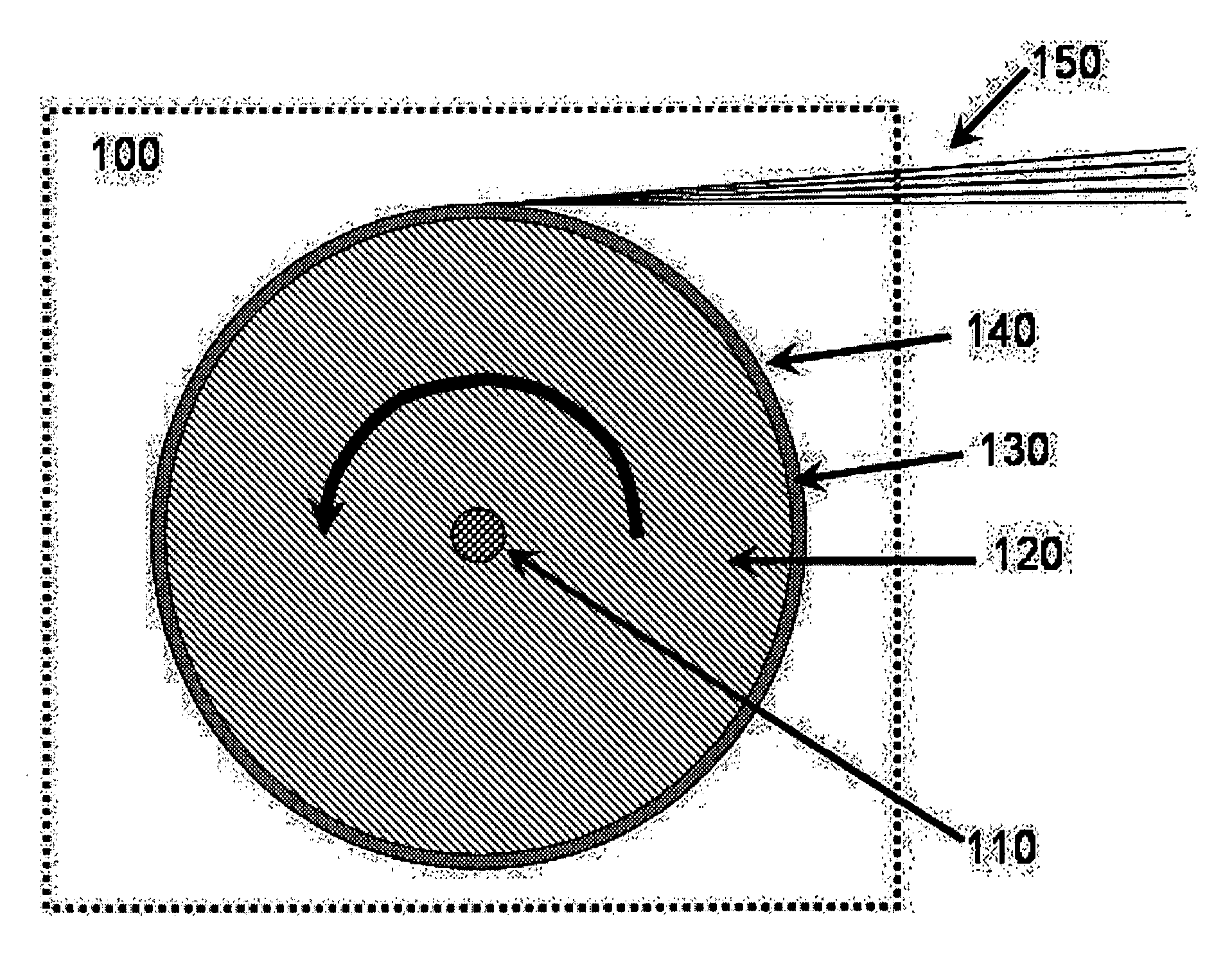
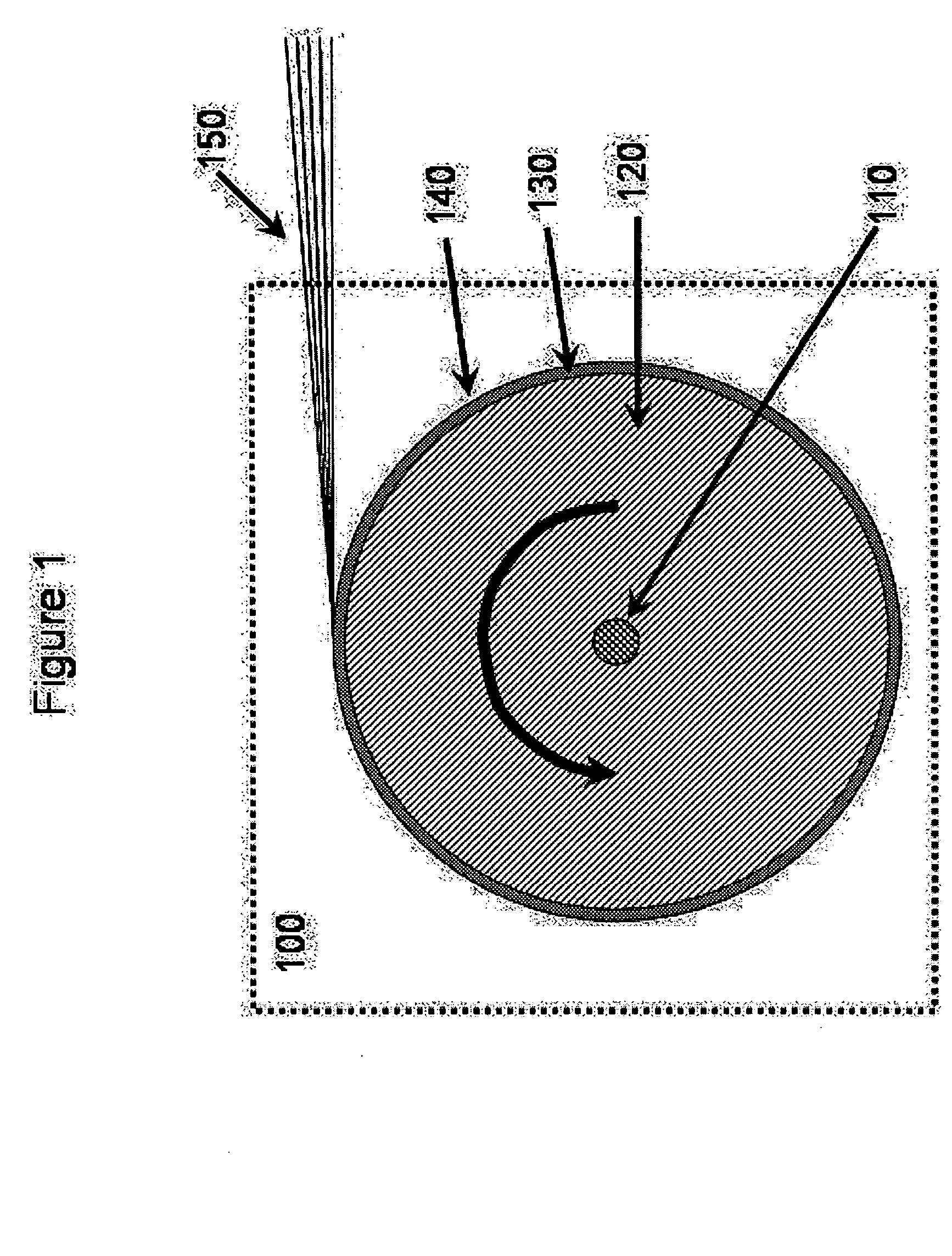
[0025] Tooling may be used to fabricate parts, including composite parts, of various types, shapes, sizes and materials with a high dimensional accuracy. The design of the tooling typically is dependent on the desired shape of the part to be formed, the materials used to form the part, the amount of strength and rigidity which the tooling must have to support the materials necessary for forming the part, and / or the method used to provide the materials for forming the part.

[0026] Tools encompass one or more surfaces, referred to as tool faces, upon which material is formed, shaped, molded, or otherwise produced into a part(s) having a surface(s) of predetermined sizes and shapes. Such parts can include, but are not limited to, structures, parts, sub assemblies, portions of components, partial components, and the like, including any solid form having a shaped surface. The tool face is a surface of the tool body, typically formed such that it is a precise three dimensional negative mi...


PUM

PropertyMeasurementUnit
temperatureaaaaaaaaaa

Abstract

Tools for the forming of composite parts from composite forming materials, having tool bodies that comprise, at least in part, carbon foam where a surface of the carbon foam may comprise a tool face or supports tool face materials. The tools of the present invention may be lighter, more durable, and less costly to produce and/or use than conventional tools used for the production of composite parts, particularly those tools used for the production of carbon composites. Additionally, such tools may be reusable, repairable, and more readily modifiable.

Description

[0001] This application claims the benefit of and is a continuation-in-part of U.S. patent application Ser. No. 09 / 941,342 filed Aug. 29, 2001, which is a continuation-in-part of U.S. patent application Ser. No. 09 / 453,729 filed Dec. 12, 1999 and U.S. patent application Ser. No. 09 / 902,828, filed Jul. 10, 2001; and this application claims the benefit of U.S. Provisional Patent Application No. 60 / 536,999, filed on Jan. 19, 2004, all of these applications are incorporated by reference for all purposes as if fully set forth herein.FIELD OF INVENTION [0002] This invention relates to composite tooling and methods for using the same, more specifically incorporating carbon foam in a tool body for forming parts made from composite materials. BACKROUND OF THE INVENTION [0003] Generally, composite materials are prepared by imbedding a reinforcing material within a matrix material. Composite materials having high degrees of utility typically exhibit mechanical or other properties superior to t...

Claims


Application Information

Patent Timeline
Patent Type & Authority Applications(United States)
IPC IPC(8): B29C70/44B29C70/54B32B5/16
CPCB29C70/443Y10T428/30B32B5/16B29C70/542
Inventor JOSEPH, BRIAN E.MERRIMAN, DOUGLAS J.LUCAS, RICK D.
Owner TOUCHSTONE RES LAB
Why Eureka
Try Eureka