
Method and system for controlling locomotives

Inactive Publication Date: 2005-01-13
GENERAL ELECTRIC CO
View PDF18 Cites 92 Cited by
  • Summary
  • Abstract
  • Description
  • Claims
  • Application Information

AI Technical Summary

Problems solved by technology

However, such systems typically require rail yard personnel to actively control movement of the locomotive via the OCU.

Method used


Image

  • Method and system for controlling locomotives
  • Method and system for controlling locomotives
  • Method and system for controlling locomotives

Examples


Embodiment Construction

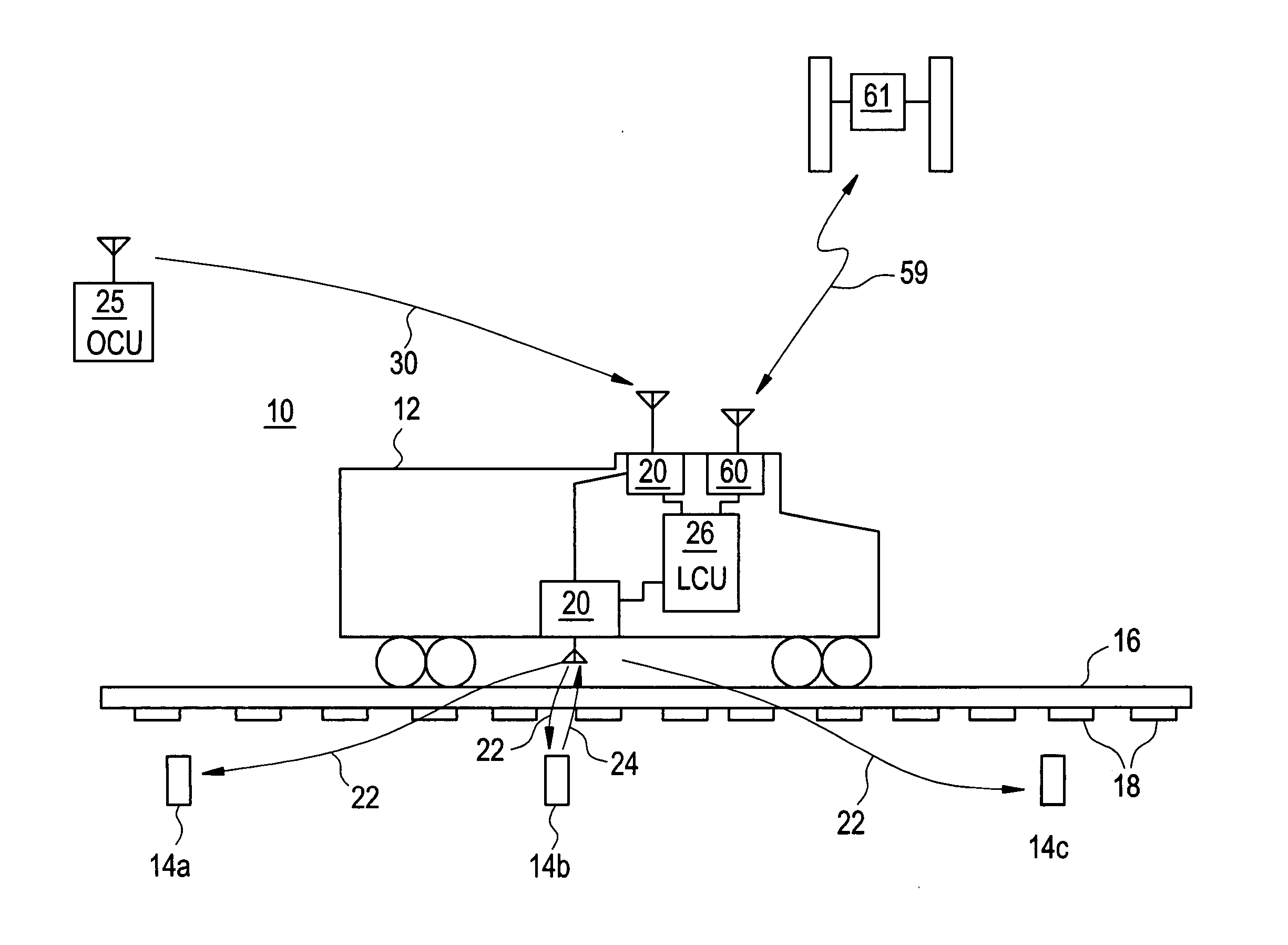
[0009] It is known to track train cars using automatic equipment identifier (AEI) systems that include a transponder mounted to each car as well as each locomotive in the train. A transponder reader is positioned at a strategic point along the rail to identify each transponder-equipped car when the car passes the reader. However, control of the operation of the movement of the train based on such information requires a complex communications and data processing network, which often involves operator interaction.

[0010] In contrast, the present inventors have innovatively realized that transponders may be placed at strategic locations along a rail track and encoded with desired locomotive movement information, for example, corresponding to the location of the transponder, and used to provide another mode of operation that is more direct. A locomotive configured with a reader may receive the movement information from each of the transponders that the locomotive passes and movement of ...


PUM


Abstract

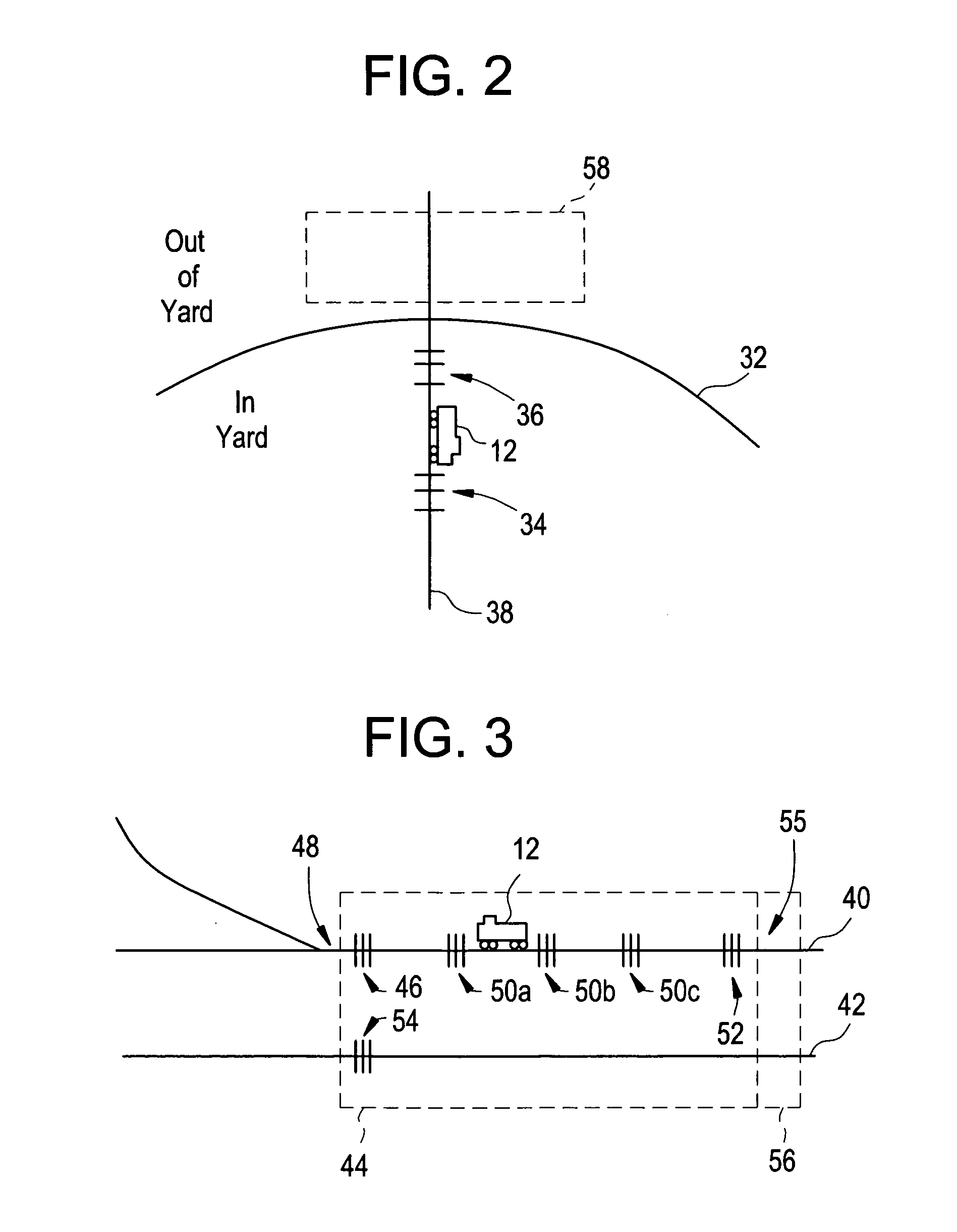
A method and system (10) for self-directed operation of a locomotive (12) in a rail yard (82) using a control system (64) on the locomotive for controlling locomotive operations. The method includes establishing at least one operational area (e.g. 74, 76, 78) within the rail yard and associating an operational parameter with each area. The method also includes operating the locomotive using the control system and sensing a location of the locomotive within an operational area. The method further includes determining whether the locomotive is operating within the operational parameter established for the area of its location. If the locomotive is determined not to be operating within the operational parameter, an operation of the locomotive is automatically controlled to operate within the respective operational parameter, without operator input to the control system. The system includes a location detector (62) in communication with the control system to automatically control locomotive operation.

Description

[0001] This application claims priority to U.S. Provisional Application Ser. No. 60 / 474,151, filed on May 22, 2003 and U.S. Provisional Application Ser. No. 60 / 528,021, filed on Dec. 9, 2003, both of which are incorporated herein by reference.FIELD OF THE INVENTION [0002] This invention relates generally to the field of locomotives, and more particularly to automatically controlling locomotives in a rail yard responsive to a sensed position of the locomotive. BACKGROUND OF THE INVENTION [0003] It is known to remotely control locomotives in a rail yard using remote radio transmitting devices controlled by rail yard personnel. Such systems may include an operator control unit (OCU) or control tower unit in remote communication with a locomotive control unit (LCU) on board the locomotive. The LCU directs the locomotive to move and stop according to transmitted commands. However, such systems typically require rail yard personnel to actively control movement of the locomotive via the OC...

Claims


Application Information

Patent Timeline
IPC IPC(8): B61L3/12B61L17/00B61L25/02
CPCB61L3/121B61L3/127B61L17/00B61L25/021B60L2200/26B61L25/025B61L25/026B61L2205/04Y02T90/16B61L25/023
Inventor KRAELING, MARK BRADSHAWPELTZ, DAVID MICHAELPELTONEN, GLEN PAULKISS, JAMESKUMAR, AJITH KUTTANNAIRPELKOWSKI, STEPHEN MATTHEWHENDRICKSON, BRADLEY CHARLESHESS, GERALD JAMES JR.BALLESTY, DANIEL MALACHIKISAK, JEFFREY JAMES
Owner GENERAL ELECTRIC CO
Learn More