Virtual collaborative editing room

a collaborative editing and virtual technology, applied in the field of virtual collaborative editing rooms, can solve the problems of post-production delay, further delay, and significant delays

Inactive Publication Date: 2005-01-13
DREAM WORKS ANIMATION
View PDF18 Cites 43 Cited by
  • Summary
  • Abstract
  • Description
  • Claims
  • Application Information

AI Technical Summary

Benefits of technology

[0010] The present invention allows for intimate collaboration and personal interaction during the editing process between parties situated in different locations. In one embodiment of the invention, a source location and a target location are connected over a network to transmit video and audio between the two locations; both locations have video and audio capture apparatuses, video displays, and audio output devices. The source location further includes, an editing system that outputs media content for transmission to a target location during an editing session. The target location includes, a remote playback controller that an operator, such as a director, uses to view the media content on the video display and control the playback of the media content on the editing system at the source location. In addition, both the target and source locations include a computer system enabling both operators to overlay graphics, text, or other information on the media content; this additional information is transmitted from one location to the other where it can be viewed by the other operator as overlays on the media content display on the second location's video display.
[0011] Preferably, at least one location, such as the target location, includes a virtual eye-to-eye video capture and display apparatus. This apparatus includes a video camera positioned behind a beam splitter to capture the operator's direct gaze at the video display so as to appear on the other location's video display as though the operator is looking directly at the other operator, thereby providing a sense of direct eye-to-eye contact between the operators. This perception of eye contact further enhances the working experience and sense of collaboration. The eye-to-eye capture apparatus also displays the captured images at about the scale and distance that further reinforces the feeling of personal contact.

Problems solved by technology

The problem arises in the collaborative editing process when the editor and director are not at the same location.
If the editor guesses incorrectly, post-production could be delayed while waiting for director's comments and further delayed if the product needs to be re-edited.
The delays could be significant if the director is busy and does not review the editor's work in a timely manner.
Any delay in post-production is costly.
In many cases, requiring the director to come to the editor's location is not practical or economical.
For example, it is not practical for the director to travel to the editor in the case of a distributed filmmaking company which is located in many separate facilities and has established different sites for editing, production, storyboarding, etc.
Additionally, the director's travel may not be practical or economical if the director is working on completion of other parts of the same film, or other films.
However, this approach does not give the editor and director sufficient ability to collaborate.
The director sees the rough edit on his local video monitor, but is generally limited to verbally instructing the editor as to when to start, pause or replay a section of the footage, and then must explain what further changes need to be made.
The conventional format of a video teleconference further substantially reduces the participants' perception of directly working together, since many non-verbal cues such as direct eye contact, body language, etc., are typically lost due to the low quality of the video signal and the physical arrangement of the camera and monitor.
Although this typically reduces cost and attracts more customers, it limits the overall ability to collaborate and to create a shared environment since it fails to take advantage of the ability to configure the overall design and functionality of both locations.

Method used


Image

  • Virtual collaborative editing room
  • Virtual collaborative editing room
  • Virtual collaborative editing room

Examples


Embodiment Construction

[0025] The present invention is now described more fully with reference to the accompanying figures, in which several embodiments of the invention are shown. The present invention may be embodied in many different forms and should not be construed as limited to the embodiments set forth herein. Rather these embodiments are provided so that this disclosure will be thorough and complete and will fully convey the invention to those skilled in the art.

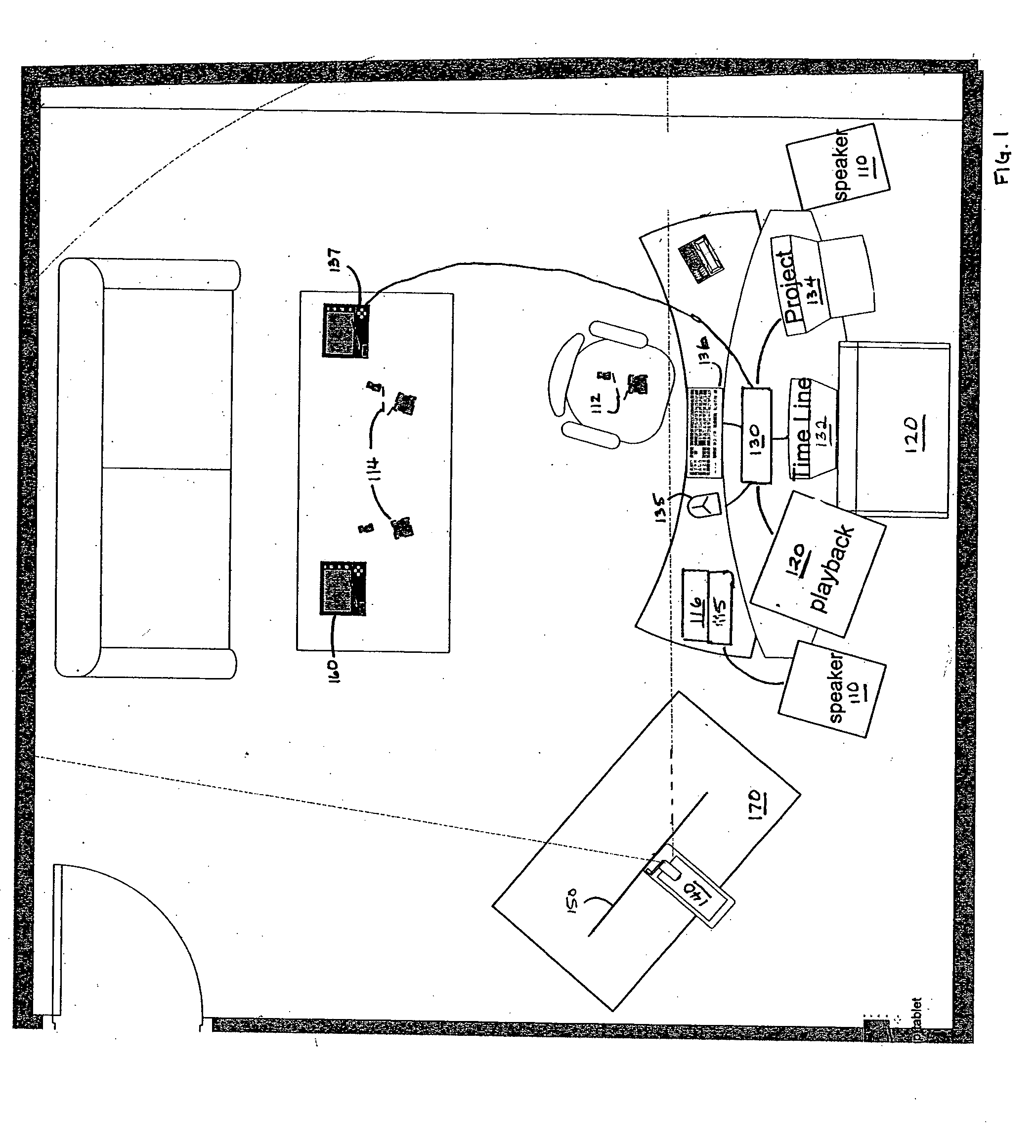
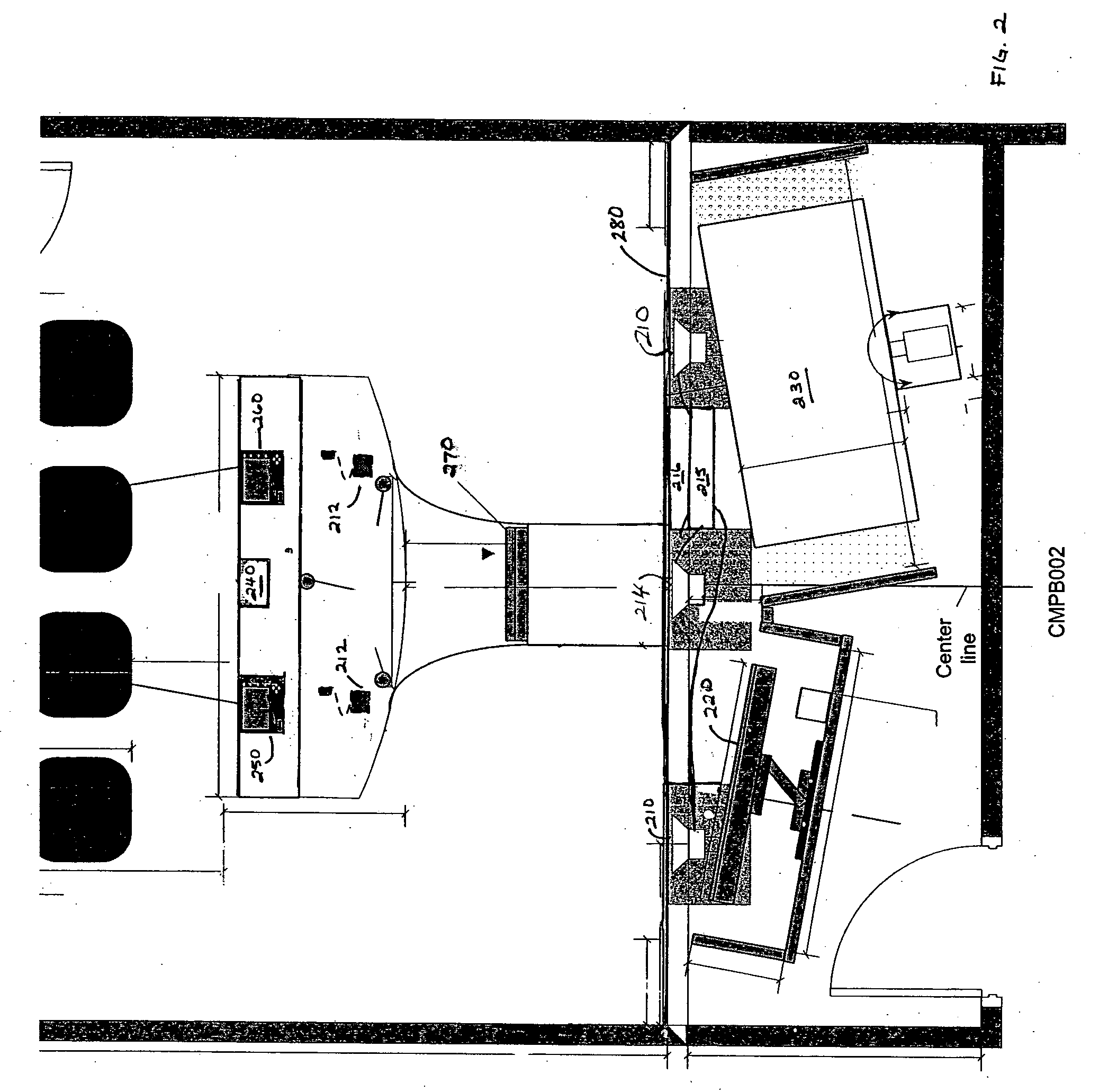
[0026] A virtual collaborative editing room generally comprises of a target location and at least one source location. The locations are communicatively coupled by a network connection. An operator at the source location produces media content. The media content can be edited video but other embodiments are possible and include, for example, media files such as static image files; audio, such as wav, mp3, etc, files; CAD / CAM files; recorded notes or any other content.

[0027] The media content is transmitted via the network to the target l...


PUM

PropertyMeasurementUnit
angleaaaaaaaaaa
angleaaaaaaaaaa
timeaaaaaaaaaa

Abstract

A room designed for collaboration and personal interaction during the editing process by parties situated in different locations. At a source location, an operator transmits media content from an editing system to a target location. At the target location, another operator uses a remote control to control the editing system's playback of the media content. The target operator can overlay graphics, text and other information on the media content. This commentary overlay is then sent back to the source location. A high-resolution video teleconferencing system allows personal real-time interaction between the source operator and target operator. The video teleconferencing system provides for direct eye-to-eye contact as well as control of audio levels for realistic conversation between the source and target operators.

Description

TECHNICAL FIELD [0001] This invention relates generally to the film editing process and, more particularly, to providing collaboration and personal interaction during editing by parties situated in different locations. BACKGROUND [0002] From the day the first scene is shot to the day the product makes it into the can, the editing process requires a precise and detailed collaborative effort from both the director and the editor. It is the director who interprets the script and oversees all creative aspects of the production. The editor selects and orders the shots into sequences to form the continuity of the story, creating drama and pacing to fulfill the director's vision of the story. In addition, the editor adds the sound, titles, transitions and special effects. The editor also reviews the dailies to ensure that all necessary shots for a sequence were taken at a particular location and to ensure that no technical problems occurred while filming (e.g., the camera was out of focus)...

Claims


Application Information

Patent Timeline
Patent Type & Authority Applications(United States)
IPC IPC(8): G09G5/00G11B27/02H04N
CPCG11B27/02
Inventor MODER, STEVENFRANCISCO, EMMANUEL C.RUBIO, RICHARDBESHEARS, JAMES F.
Owner DREAM WORKS ANIMATION
Why Eureka
Try Eureka