Spring-loaded slot door latching bar

a latching bar and spring-loaded technology, applied in the field of moneyboxes, can solve problems such as the risk of possible injury

Inactive Publication Date: 2005-01-20
VIEJAS BAND OF KUMEYAAY INDIANS
View PDF6 Cites 0 Cited by
  • Summary
  • Abstract
  • Description
  • Claims
  • Application Information

AI Technical Summary

Benefits of technology

[0010] The present invention consists of a spring-loaded slot door latching bar comprised of a handgrip on one end of a central bar member with a pivot pin located in the opposite end whereby a pressure arm and an engagement arm pivot in unison when the spring-loaded slot door latching bar is pushed in a downward direction against the spring-loaded door mechanism and the inside wall section of the moneybox. The pressure arm is composed of a straight section and an angled portion. The pressure arm has a bent tab adjacent to the pivot pin limiting the pivoting travel and keeping the pressure arm within the operational position. The engagement arm has a straight section with a relieved area that has a rounded distal end. The relieved area of the pressure arm maintains clearance for the rounded distal end to pass under the latching members and the latching mechanisms on the spring loaded door mechanism of a moneybox or similar container. The rounded distal end may be coated with a smooth material or covered with a Teflon cap to produce a smooth wearing surface and still remain within the scope of this patent. The engagement arm has a bent tab adjacent to the pivot pin limiting the pivoting travel and keeping the engagement arm within the operational position. By the introduction of the bent tabs on the spring-loaded slot door-latching bar, the device is maintained in a vertical position when placed into a moneybox or similar container. When the spring-loaded slot door latching bar is pushed in a downward direction there is enough spacing in the bent tabs, and enough mechanical advantage to allow the pressure arm and the engagement arm to easily spread in a scissor-like action to successfully compress the springs in the spring-loaded door mechanism.

Problems solved by technology

Further, the spring-loaded mechanism is at the opposite end of the compartment from the door and at a difficult angle to get enough leverage on to conveniently push the pressure plate thereby latching the mechanism.
Consequently there exists a need for an apparatus, which easily will perform the task of latching the spring-loaded door mechanisms on moneyboxes and like storage containers without forcing the users hand or arm down into the compartments with the risk of possible injury.

Method used


Image

  • Spring-loaded slot door latching bar
  • Spring-loaded slot door latching bar
  • Spring-loaded slot door latching bar

Examples


Embodiment Construction

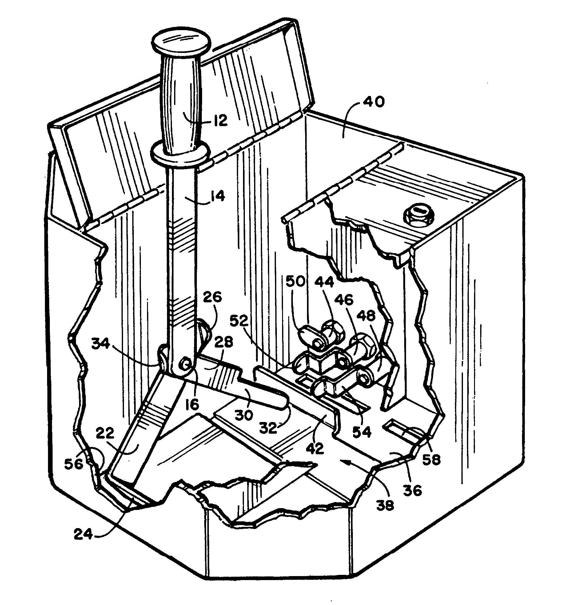
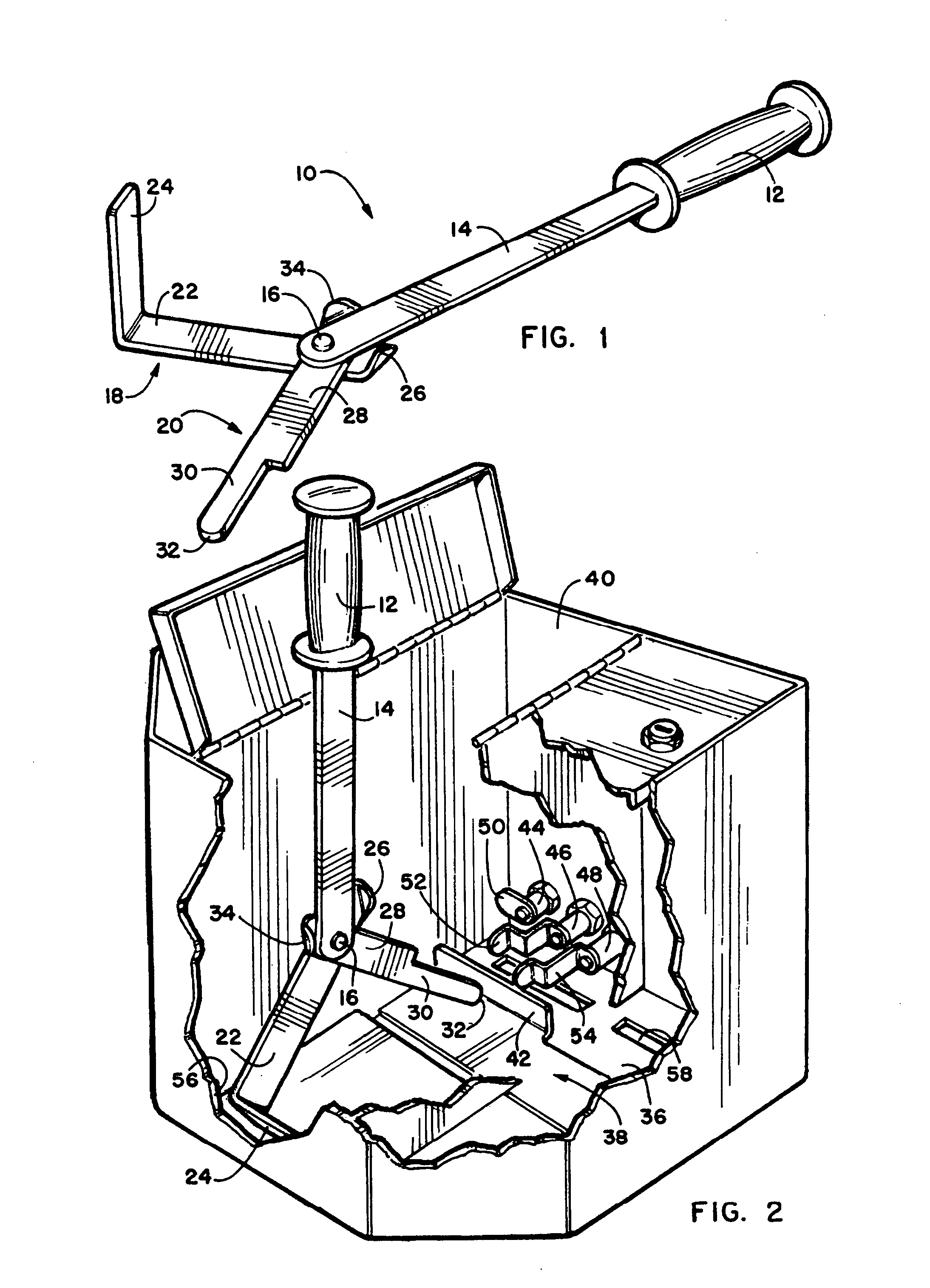
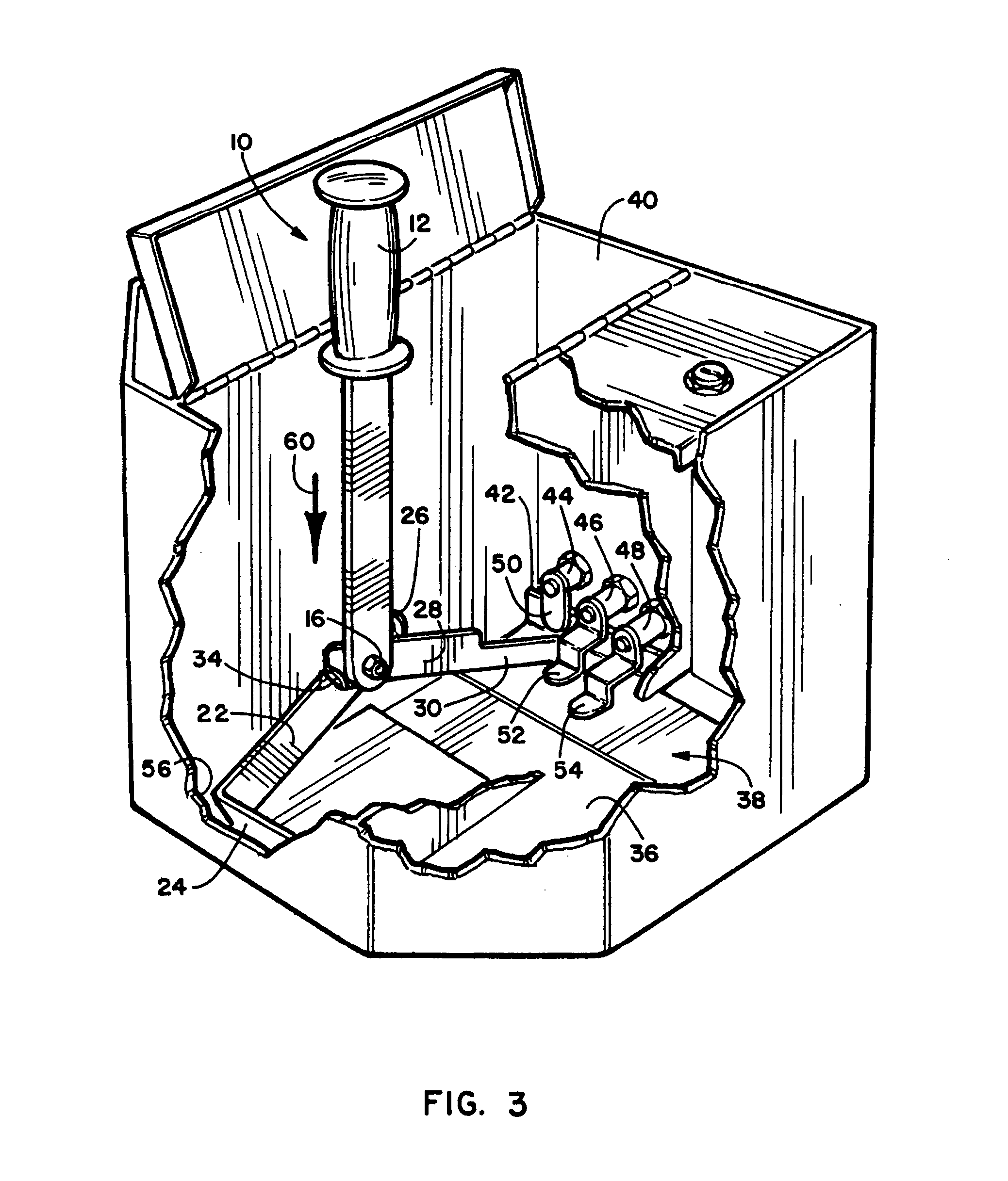
[0022] Referring now to the drawings, wherein similar parts of the invention are identified by like reference numerals, there is seen in FIG. 1 a perspective view of the spring-loaded slot door latching bar or tool 10 comprised of a handgrip 12 and a central bar member 14. At the distal end of the central bar member 14 is located a pivot pin 16 whereby a pressure arm 18 and an engagement arm 20 pivot in unison when the spring-loaded slot door latching bar 10 is pushed in a downward direction. The pressure arm 18 is composed of a pressure arm straight section 22 with an angled portion 24. The pressure arm 18 has a bent tab 26 adjacent to the pivot pin 16 limiting the pivoting travel and keeping the pressure arm 18 within the operational position. The engagement arm 20 has an engagement arm straight section 28 with a relieved area 30 that has a rounded distal end 32. The rounded distal end 32 may be coated with a smooth material or covered with a Teflon cap to produce a smooth wearing...


PUM


Abstract

With the advent of this new and unique spring-loaded slot door latching bar the individuals involved in the operation of removing the contents of the moneyboxes and the like will have at their disposal a device that by inserting and pushing down on the bar handgrip, the latching mechanism will be set and then, by turning the three separate keys the latches will be relocated in place holding the door mechanism. This rapid and safe operation will easily speed up the operation and eliminate a lot of skinned knuckles.

Description

FIELD OF THE INVENTION [0001] This invention relates to the field of moneyboxes used at gaming tables or other facilities where an individual is required to insert currency into one or more compartments within a box unit whereby the currency cannot be retrieved without removing the box and unlocking the compartments to remove the contents. This invention provides a spring-loaded slot door latching bar whereby an individual, after removing the contents, can easily re-latch the spring-loaded door mechanisms by simply pushing straight down on the unique moneybox spring-loaded slot door-latching bar and turning the latching mechanism keys into their respective locked positions. BACKGROUND OF THE INVENTION [0002] At gaming tables and the like, when a player desires to purchase playing chips, they give the dealer currency, normally bills to pay for the chips. The bills are then placed over a slot in a concealed container and then the dealer uses a blade tool to insert the bill through a s...

Claims


Application Information

Patent Timeline
Patent Type & Authority Applications(United States)
IPC IPC(8): B25B27/00B25B33/00
CPCB25B33/00B25B27/00Y10T292/0832Y10T292/0908
Inventor PANEK, DAVID J.SILVA, AL
Owner VIEJAS BAND OF KUMEYAAY INDIANS
Why Eureka
Try Eureka