
Method of and apparatus for cracking connecting rod

Inactive Publication Date: 2005-01-20
HONDA MOTOR CO LTD
View PDF15 Cites 21 Cited by
  • Summary
  • Abstract
  • Description
  • Claims
  • Application Information

AI Technical Summary

Benefits of technology

[0009] It is a general object of the present invention to provide a method of and an apparatus for cracking a connecting rod with a simplified and inexpensive overall apparatus structure and an increased production efficiency.

Problems solved by technology

The apparatus is also complex because of ancillary equipment required to supply and discharge the pressurizing liquid.
Therefore, the apparatus is inevitably costly to manufacture.
As the number of connecting rods 5 to be processed increases, the operation to insert the pressurizing hose 8 through the larger end holes 3a in the connecting rods 5 becomes more tedious and time-consuming, resulting in a reduction in the production efficiency with which to crack the connecting rods 5.

Method used


Image

  • Method of and apparatus for cracking connecting rod
  • Method of and apparatus for cracking connecting rod
  • Method of and apparatus for cracking connecting rod

Examples


Embodiment Construction

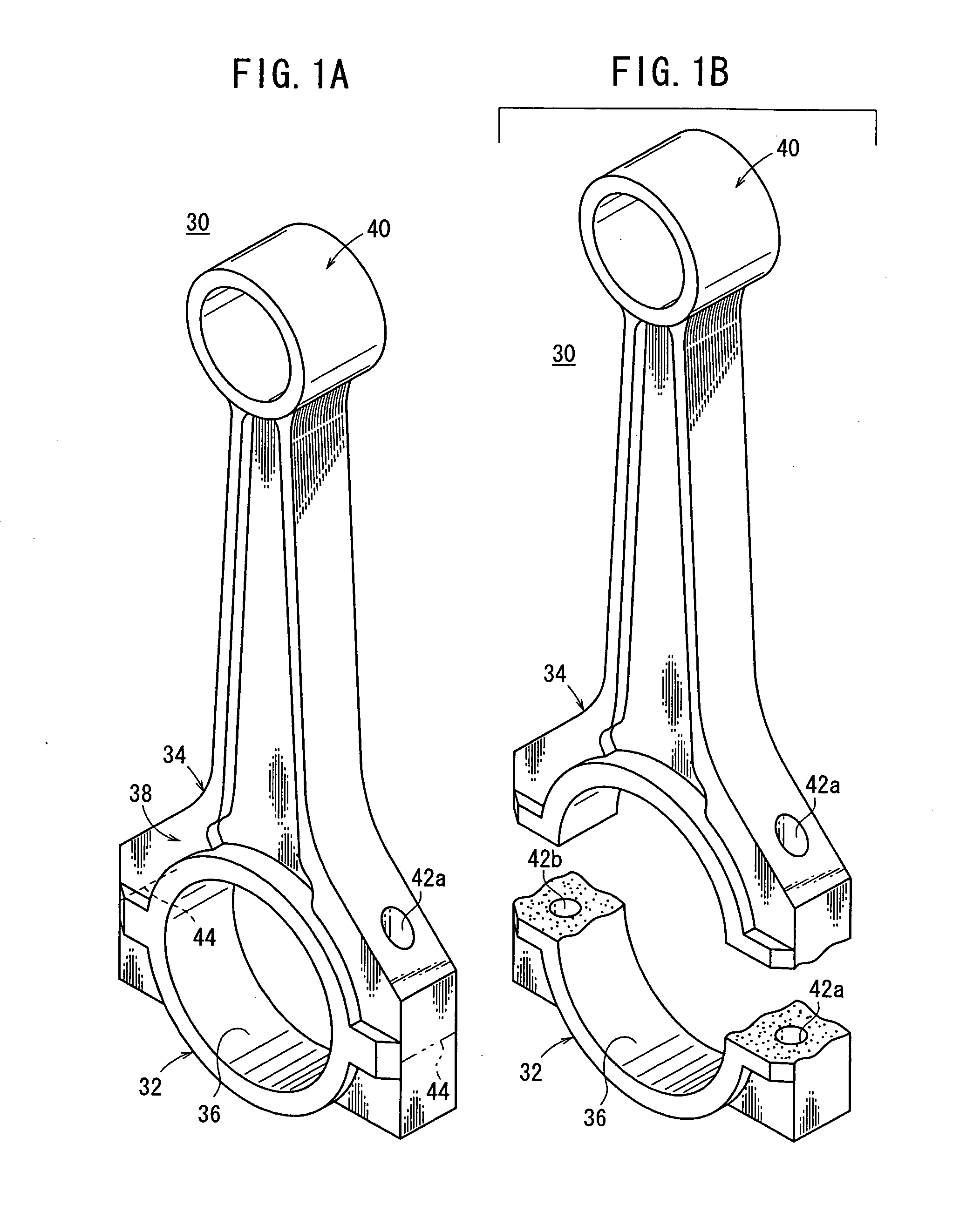
[0021]FIG. 1A shows in perspective a connecting rod 30 as a workpiece to which the present invention is applied, and FIG. 1B shows in perspective the connecting rod 30 as it is fractured into a cap 32 and a rod 34.

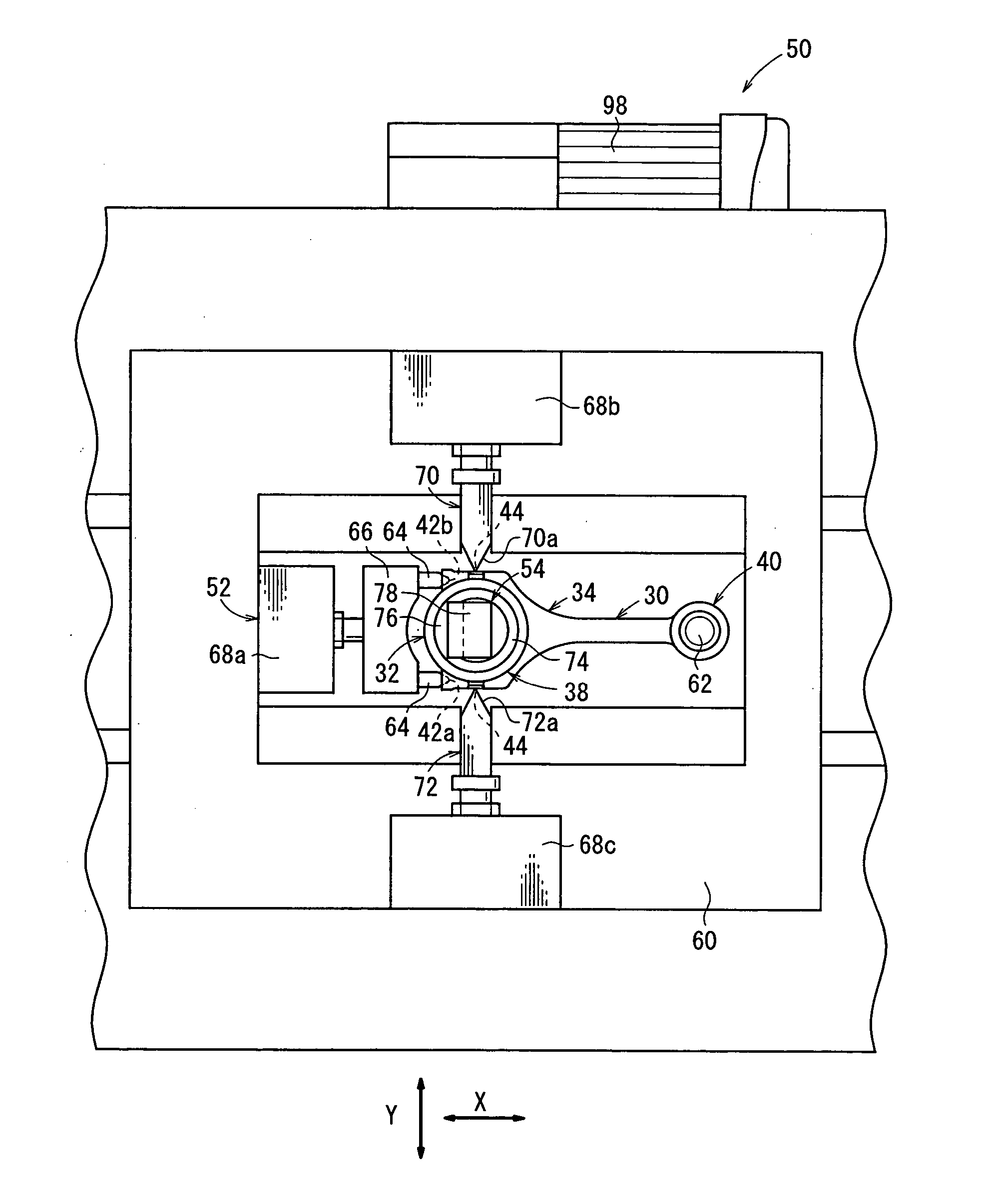
[0022] As shown in FIGS. 1A and 1B, the connecting rod 30 has a larger end 38 comprising an integral structure of the cap 32 and the rod 34 with a substantially circular joint hole 36 defined therebetween, and a smaller end 40 positioned remotely from the larger end 38. The connecting rod 30 may be integrally produced by casting, forging, or the like.

[0023] The larger end 38 has a pair of bolt holes 42a, 42b defined in opposite sides thereof by a boring means such as a drill or the like. In a process of assembling an engine, bolts (not shown) are threaded from the cap 32 into the respective bolt holes 42a, 42b, fastening the cap 32 to the rod 34. The fractured cap 32 is thus fastened to the rod 34 to connect the larger end 38 of the connecting rod 30 to a crank pin of th...


PUM

PropertyMeasurementUnit
Weightaaaaaaaaaa
Gravityaaaaaaaaaa

Abstract

A preload is applied to a wedge pressed in between a pair of spreaders by a preloading mechanism to press the spreaders against an inner surface of a joint hole defined in a larger end of a connecting rod. While the spreaders are pressed against the inner surface of the joint hole, a movable table with weights placed thereon is caused to drop into impingement against a flange coupled to an end of a shaft. The shaft is pulled downwardly to apply an impact load to the wedge, which is coupled to the shaft, in the direction in which the wedge is pressed in, thereby fracturing the larger end into a cap and a rod.

Description

BACKGROUND OF THE INVENTION [0001] 1. Field of the Invention [0002] The present invention relates to a method of and an apparatus for cracking a connecting rod as an engine component for vehicles, and more particularly to a method of and an apparatus for cracking a one-piece connecting rod having a larger end and a smaller end to fracture the larger end into a cap and a rod. [0003] 2. Description of the Related Art [0004] Heretofore, connecting rods interconnecting piston pins and crank pins have widely been used in vehicular engines. Each of the connecting rods has a larger end coupled to the crankpin and a smaller end coupled to the piston pin. For manufacturing a connecting rod, it is generally customary to produce a one-piece connecting rod having a larger and a smaller end and thereafter to fracture the larger end into a cap and a rod. [0005] One conventional process of fracturing a connecting rod will be described below. [0006] As shown in FIG. 8 of the accompanying drawings, ...

Claims


Application Information

Patent Timeline
IPC IPC(8): B23D31/00F16C7/00F16C9/04
CPCF16C9/045B23D31/003Y10T225/30Y10T225/371Y10T225/10
Inventor MOMOSE, YASUOOTA, SIGEOYAMAMOTO, TOMOHIKO
Owner HONDA MOTOR CO LTD
Learn More