
Method of producing a ceramic body by coalescence and the ceramic body produced

a technology of ceramic body and coalescence, which is applied in the field of producing ceramic body by coalescence and ceramic body, can solve the problems of long setting time, poor flexibility when integrating with other machines, and complicated use of spring-actuated percussion machines, and achieve the effect of low cost and efficient production of products

Inactive Publication Date: 2005-01-20
OLSSON KENT +1
View PDF0 Cites 25 Cited by
  • Summary
  • Abstract
  • Description
  • Claims
  • Application Information

AI Technical Summary

Benefits of technology

The object of the present invention is to achieve a process for efficient production of products from ceramic at a low cost. These products may be both medical devices such as medical implants or bone cement in orthopaedic surgery, instruments or diagnostic equipment, or non medical devices such as tools, insulator applications, crucibles, spray nozzles, tubes, cutting edges, jointing rings, ball bearings and engine parts. Another object is to achieve a ceramic product of the described type.
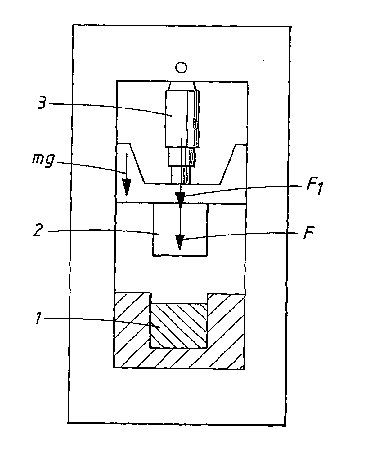
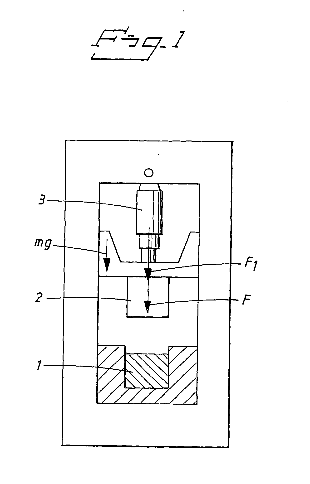
The method according to the invention utilises hydraulics in the percussion machine, which may be the machine utilised in WO-A1-9700751 and SE 9803956-3. When using pure hydraulic means in the machine, the striking unit can be given such movement that, upon impact with the material to be compressed, it emits sufficient energy at sufficient speed for coalescence to be achieved. This coalescence may be adiabatic. A stroke is carried out quickly and for some materials the wave in the material decay in between 5 and 15 milliseconds. The hydraulic use also gives a better sequence control and lower running costs compared to the use of compressed air. A spring-actuated percussion machine will be more complicated to use and will give rise to long setting times and poor flexibility when integrating it with other machines. The method according to the invention will thus be less expensive and easier to carry out. The optimal machine has a large press for pre-compacting and post-compacting and a small striking unit with high speed. Machines according to such a construction are therefore probably more interesting to use. Different machines could also be used, one for the pre-compacting and post-compacting and one for the compression.

Problems solved by technology

A spring-actuated percussion machine will be more complicated to use and will give rise to long setting times and poor flexibility when integrating it with other machines.

Method used


Image

  • Method of producing a ceramic body by coalescence and the ceramic body produced
  • Method of producing a ceramic body by coalescence and the ceramic body produced
  • Method of producing a ceramic body by coalescence and the ceramic body produced

Examples


example 1

Table 1 shows the properties for the ceramic types used.

TABLE 1PropertiesSilicone nitrideHydroxyapatiteAluminaZirconia 1. Particle size<0.5<1<0.50.4   (micron) 2. Particle<0.5<10.3-0.5<0.6   distribution   (micron) 3. ParticleIrregularirregularirregularirregular   morphology 4. PowderFreeze-dryWet chemistryGrindingSpray-dry   productiongranulationprecipitationFreeze-drygranulationgranulation 5. Crystal structure98% alfaApatitealfatetragonal2% beta(hexagonal) 6. Theoretical3.18 (batch 1, 2)3.15 g / cm33.98 (batch 1)6.07   density (g / cm3)3.27 (batch 3)3.79 (batch 2)3.12 (batch 4)3.98 (batch 3)3.79 (batch 4) 7. Apparent0.380.60.5-0.8—   density (g / cm3) 8. Melt1800160020502500-2600   temperature   (° C.) 9. Sintering18209001600-16501500   temperature   (° C.)10. Hardness (HV)157045017701250-1350

An exterior lubrication with Acrawax C was used for all batches. Further, for silicone nitride and alumina 1.5 vol % PEG 400 (plasticiser), 5 vol % PVA (binder) an...

example 2

In the following parameter studies performed on silicon nitride and HA are described.

Multi stroke Sequence Parameter Study of Silicon Nitride (C-E)

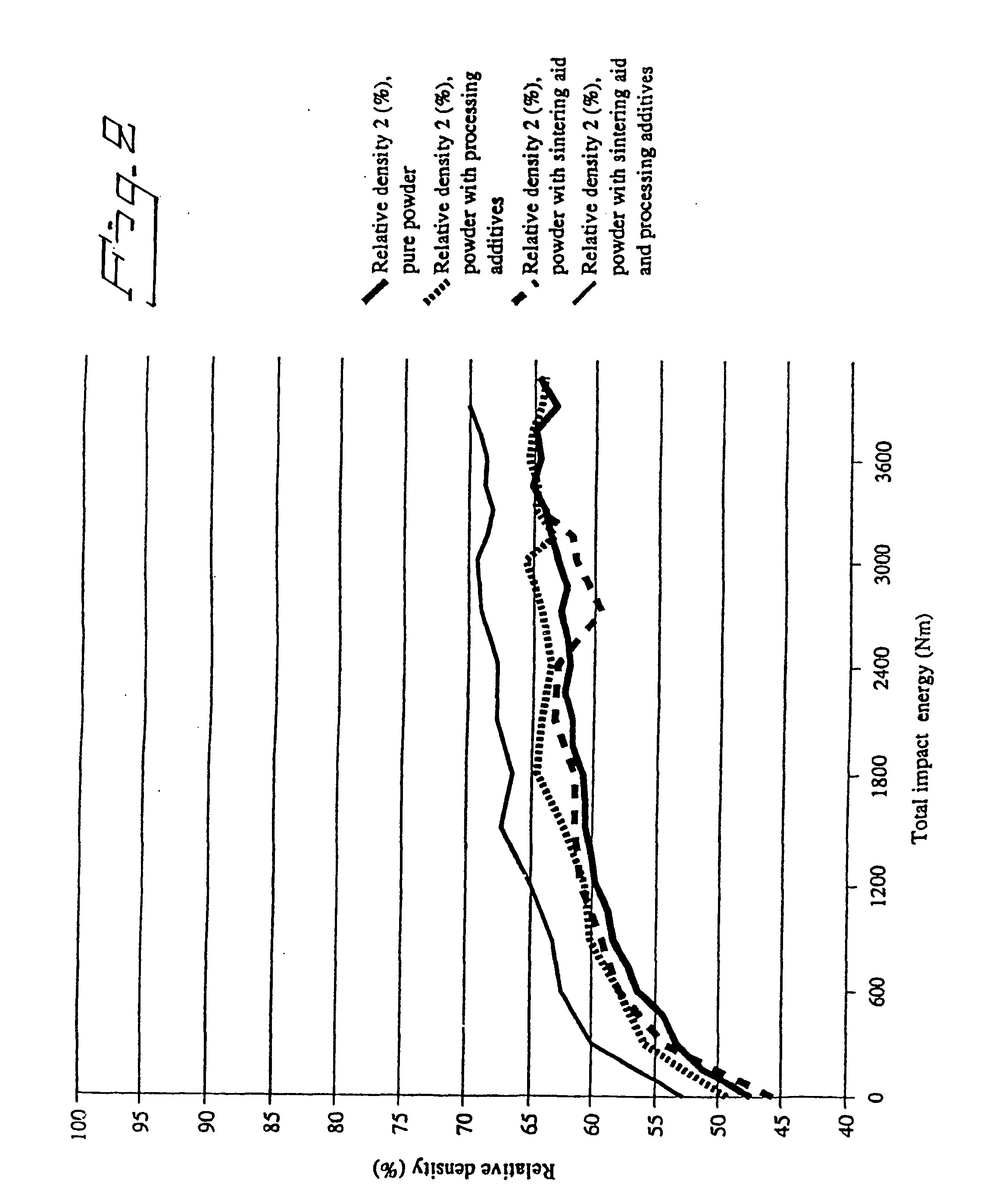
Silicon nitride powder was compressed in different multi-stroke sequences ranging from two to six strokes with total energy levels from 2400 to 18000 Nm. The study is divided into two parts. The first study the sample's density as the total impact energy increases by adding the number of strokes. The individual stroke energy was 3000 Nm and performed from one to six strokes, i.e. the total impact energy was ranging from 3000 to 18000 Nm. Additional sequences were performed for the two stroke sequences with individual stroke energies of 1200, 2400, 3300 and 6600.

The results are shown i FIGS. 9-12.

In FIG. 9 the relative density is plotted as function of total impact energy for the series with individual impact energy of 3000 Nm for one to six strokes. The total impact energy is the sum of the individual impact energy in a stroke ser...

example 3

The tests were performed with hydroxyapatite.

When a sample is produced it must automatically and quickly be dismounted from the tool. Thereafter the next sample should be produced, without the need of any preparation, like polishing, of the tool surfaces. In the above tests the used lubricant, Acrawax C, rendered material rests on the tool surfaces at high impact energies for some material types.

There will also be tested how different lubricants affect the obtained relative density. According to the literature the friction against the tool walls causes a pressure fall from the moving stroke unit and that decreases the compression of the powder and correspondingly also the density.

Several types of lubricants are tested. The amount of graphite, two types of graphite, the amount of boron nitride in grease, the viscosity are all tested to determine the behaviour of each parameter.

The powder used has not been pre-processed.

Each lubrication type was applied on the tool surfaces...


PUM

PropertyMeasurementUnit
pressureaaaaaaaaaa
areaaaaaaaaaaa
diameteraaaaaaaaaa

Abstract

A method of producing a ceramic body by coalescence, wherein the method comprises the steps of a) filling a pre-compacting mould with ceramic material in the form of powder, pellets, grains and the like, b) pre-compacting the material at least once and c) compressing the material in a compression mould by at least one stroke, where a striking unit emits enough kinetic energy to form the body when striking the material inserted in the compression mould, causing coalescence of the material. A method of producing a ceramic body by coalescence, wherein the method comprises compressing material in the form of a solid ceramic body in a compression mould by at least one stroke, where a striking unit emits enough energy to cause coalescence of the material in the body. Products obtained by the inventive methods.

Description

The invention concerns a method of producing a ceramic body by coalescence as well as the ceramic body produced by this method. STATE OF THE ART In WO-A1-9700751, an impact machine and a method of cutting rods with the machine is described. The document also describes a method of deforming a metal body. The method utilises the machine described in the document and is characterised in that a metallic material either in solid form or in the form of powder such as grains, pellets and the like, is fixed preferably at the end of a mould, holder or the like and that the material is subjected to adiabatic coalescence by a striking unit such as an impact ram, the motion of the ram being effected by a liquid. The machine is thoroughly described in the WO document. In WO-A1-9700751, shaping of components, such as spheres, is described. A metal powder is supplied to a tool divided in two parts, and the powder is supplied through a connecting tube. The metal powder has preferably been gas-at...

Claims


Application Information

Patent Timeline
Patent Type & Authority Applications(United States)
IPC IPC(8): A61L27/42A61L27/44A61L27/00B22F3/087B22F3/17B22F7/06B28B3/02B29C43/00B29C43/14B29C43/16B29C43/32B29K23/00B29K33/04B29K103/00B29K105/16B29L31/00B30B11/00B30B11/02C22C1/05
CPCA61L27/42A61L27/44B29C43/006B29C43/14B29C43/146B29L2031/7532B29K2023/0683B29K2033/12B29K2033/18B29K2105/251B29C43/16
Inventor OLSSON, KENTLI, JIANGUO
Owner OLSSON KENT
Learn More