
Method of producing a polymer body by coalescence and the polymer body produced

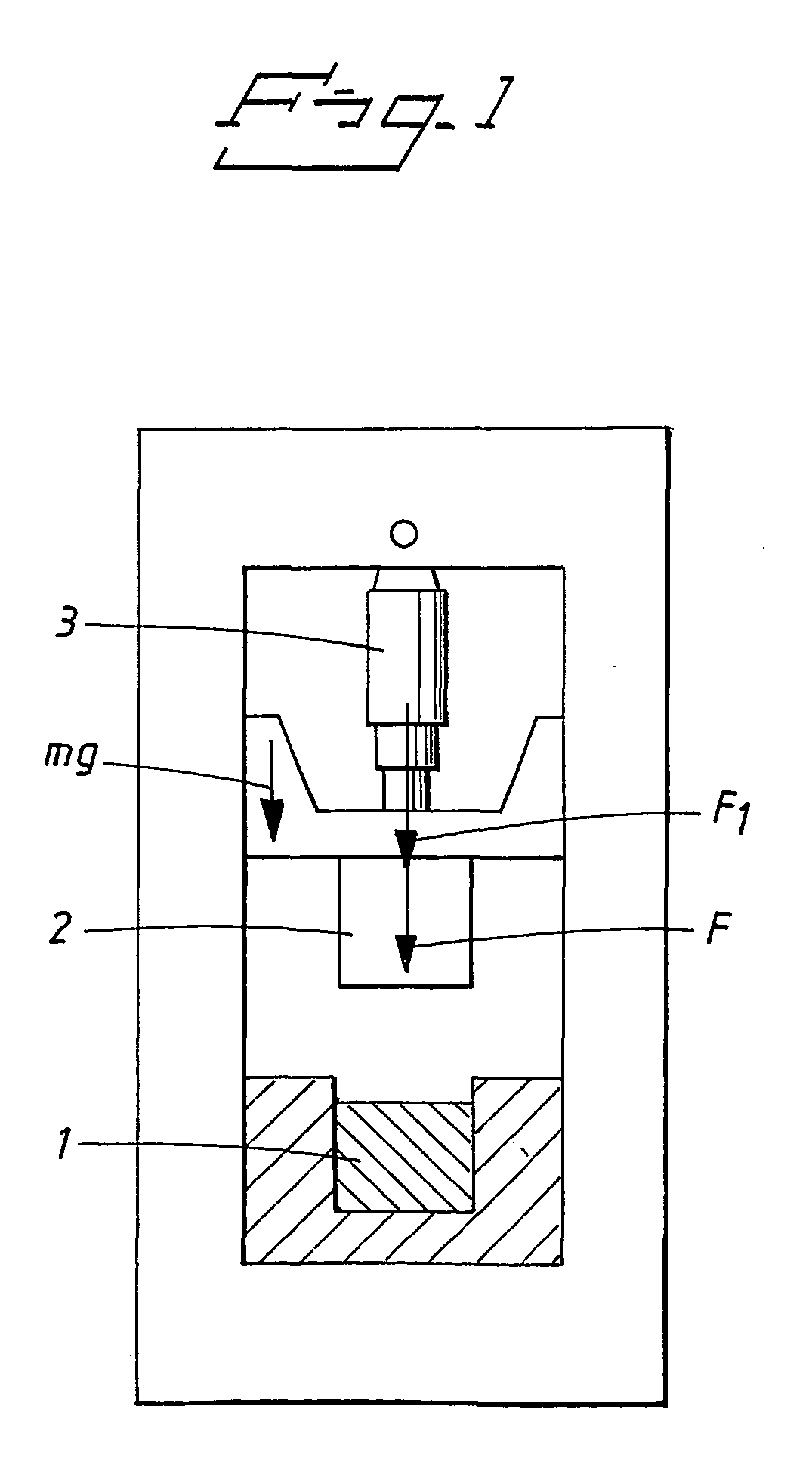
Inactive Publication Date: 2004-08-26
OLSSON KENT AL +1
View PDF0 Cites 5 Cited by
  • Summary
  • Abstract
  • Description
  • Claims
  • Application Information

AI Technical Summary

Benefits of technology

[0010] The object of the present invention is to achieve a process for efficient production of products from polymer at a low cost. These products may be both medical devices such as medical implants or bone cement in orthopaedic surgery, instruments or diagnostic equipment, or non medical devices such as sinks, baths, displays, glazing (especially aircraft), lenses and light covers. Another object is to achieve a polymer product of the described type.

Problems solved by technology

A spring-actuated percussion machine will be more complicated to use and will give rise to long setting times and poor flexibility when integrating it with other machines.

Method used


Image

  • Method of producing a polymer body by coalescence and the polymer body produced
  • Method of producing a polymer body by coalescence and the polymer body produced
  • Method of producing a polymer body by coalescence and the polymer body produced

Examples


example 1

[0112] Table 1 shows the properties for the polymer types used.

1TABLE 1 Nitrile Properties UHMWPE PMMA Rubber 1. Particle size (micron) <150 <600 <1 mm 2. Particle distribution (micron) -- -- -- 3. Particle morphology Irregular Irregular Irregular 4. Powder polymerisation -- -- -- 5. Crystal structure 50% a- amorphous amorphous morphous 6. Theoretical density (g / cm.sup.3)0.941.19 0.99 7. Apparent density (g / cm.sup.3) 50 60 -- 8. Melt temperature (.degree. C.) 125 125 9. Sintering temperature (.degree. C.) -- -- --10. Hardness (Rockwel) M92-100 R50-70 --

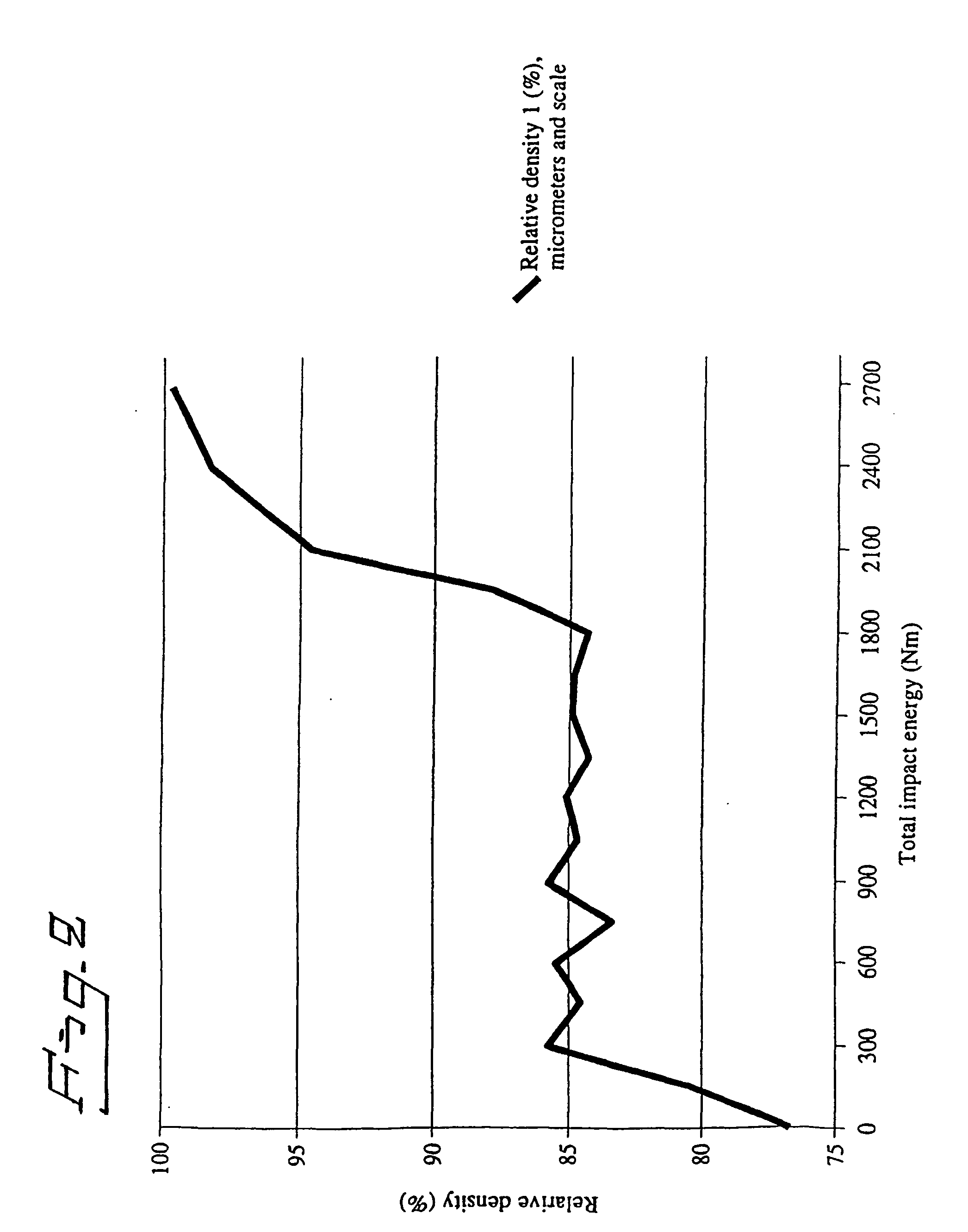
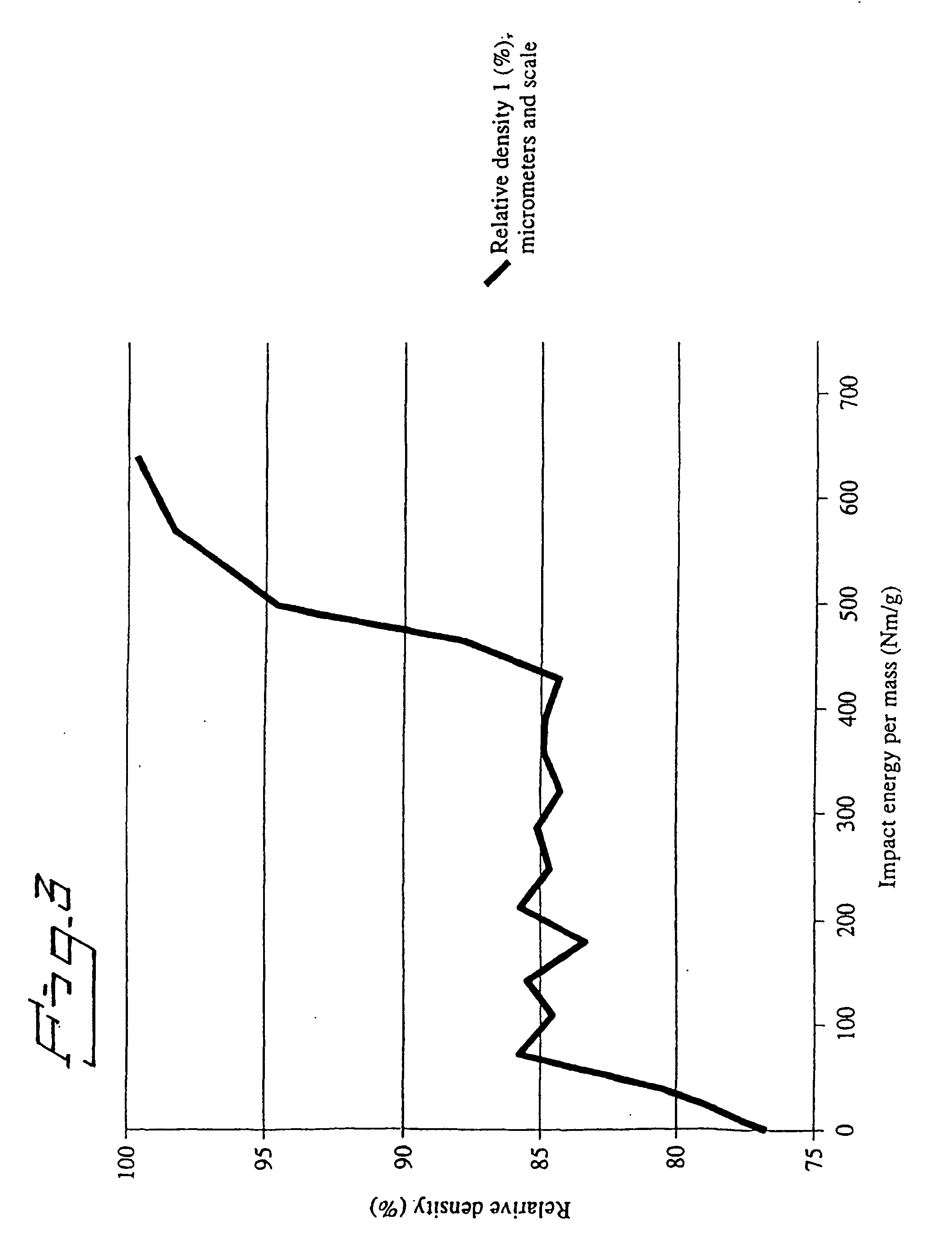
[0113] Table 2 shows the test results and the testing energy span. The density 1 method is used to establish the relative density.

2TABLE 2 Properties UHMWPE PMMA Nitrile Rubber Sample mass (g) 4.2 4.2 3.5 number of samples made 17 31 7 Energy step intervals (Nm) 150 150 300 Relative density at pre- 76.7 powder 100 compacting (%) Maximum energy (Nm) 2700 3150 2100 Energy per mass at 643 750 600 maximum density (Nm / g) Maximum relative d...

example 2

[0141] In the following parameter studies performed on UHMWPE are described. UHMWPE is a semi-crystalline, whitish and effectively opaque engineering thermoplastic which has a very high molecular weight. As a result it has an extremely high melt viscosity and it can normally only be processed by powder sintering methods. It also has outstanding toughness and cut and wear resistance and very good resistance.

[0142] UHMWPE is a common material within the implants industry. The most common application is the acetabulum, which is in contact with the hip ball.

[0143] Energy Study (C-D)

[0144] An energy study was performed using multi stroke sequences where each stroke had an impact energy of either 1200 or 2400.

[0145] Sequences of two to six strokes were investigated. The material used was pure UHMWPE powder. Prior to the impact stroke sequence the specimen were pre-compacted using a static axial pressure of 117680 N. The time interval between the strokes in a sequence was 0.4 or 0.8 s. Fiv...


PUM

PropertyMeasurementUnit
Lengthaaaaaaaaaa
Fractionaaaaaaaaaa
Fractionaaaaaaaaaa

Abstract

A method of producing a polymer body by coalescence, wherein the method comprises the steps of a) filling a pre-compacting mould with polymer material in the form of powder, pellets, grains and the like, b) pre-compacting the material at least once and c) compressing the material in a compression mould by at least one stroke, where a striking unit emits enough kinetic energy to form the body when striking the material inserted in the compression mould, causing coalescence of the material. A method of producing a polymer body by coalescence, wherein the method comprises compressing material in the form of a solid polymer body in a compression mould by at least one stroke, where a striking unit emits enough energy to cause coalescence of the material in the body. Products obtained by the inventive methods.

Description

[0001] The invention concerns a method of producing a polymer body by coalescence as well as the polymer body produced by this method.STATE OF THE ART[0002] In WO-A1-9700751, an impact machine and a method of cutting rods with the machine is described. The document also describes a method of deforming a metal body. The method utilises the machine described in the document and is characterised in that preferably metallic material either in solid form or in the form of powder such as grains, pellets and the like, is fixed preferably at the end of a mould, holder or the like and that the material is subjected to adiabatic coalescence by a striking unit such as an impact ram, the motion of the ram being effected by a liquid. The machine is thoroughly described in the WO document.[0003] In WO-A1-9700751, shaping of components, such as spheres, is described. A metal powder is supplied to a tool divided in two parts, and the powder is supplied through a connecting tube. The metal powder ha...

Claims


Application Information

Patent Timeline
IPC IPC(8): A61L27/42A61L27/00A61L27/44B22F3/087B22F3/17B22F7/06B28B3/02B29C43/00B29C43/14B29C43/16B29C43/32B29K23/00B29K33/04B29K103/00B29K105/16B29L31/00B30B11/00B30B11/02C22C1/05
CPCA61L27/42A61L27/44B29C43/006B29C43/14B29C43/146B29L2031/7532B29K2023/0683B29K2033/12B29K2033/18B29K2105/251B29C43/16
Inventor OLSSON, KENT ALLI, JIANGUO
Owner OLSSON KENT AL
Learn More