
Apparatus and method for receiving data in a mobile communication system using an adaptive antenna array scheme

a mobile communication system and antenna array technology, applied in the field of antenna array and antenna array for mobile communication systems, can solve the problems of reducing the performance of the entire mobile communication system, affecting the reception of data, and distorted transmission signals

Active Publication Date: 2005-01-20
SAMSUNG ELECTRONICS CO LTD
View PDF4 Cites 39 Cited by
  • Summary
  • Abstract
  • Description
  • Claims
  • Application Information

AI Technical Summary

Benefits of technology

It is further another object of the present invention to provide an apparatus and a method for generating a rece

Problems solved by technology

Generally, in a wireless channel environment in a mobile communication system, unlike in a wired channel environment, a transmission signal is actually distorted due to several factors, such as multipath interference, shadowing, wave attenuation, time-varying noise, interference, etc.
Therefore, the received signal suffers from severe distortion during its actual transmission, thereby reducing performance of the entire mobile communication system.
The fading may result in the distortion in the amplitude and the phase of the received signal, preventing high-speed data communication in the wireless channel environment.
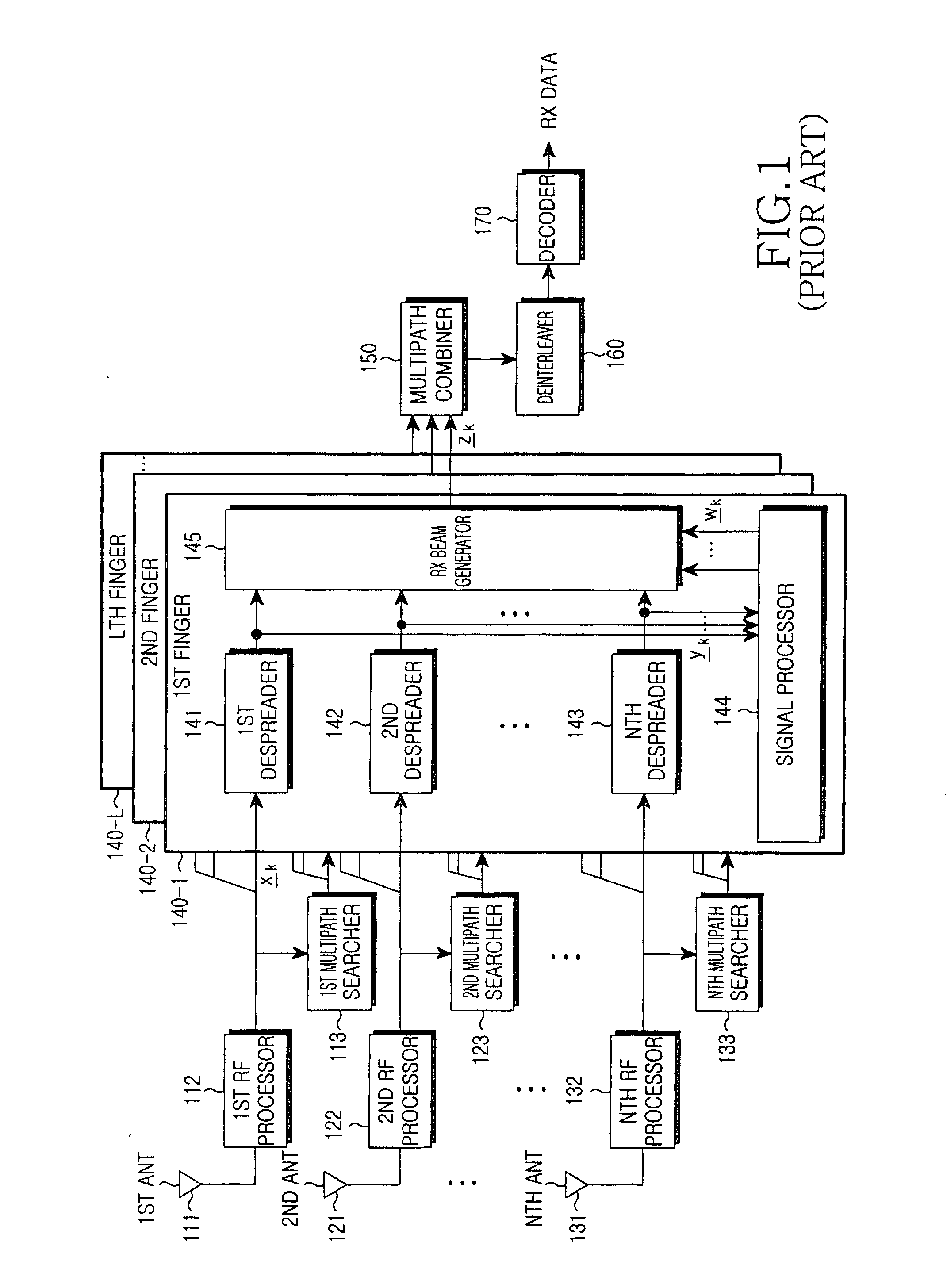
However, the Receive Diversity used in the Rake receiver is disadvantageous in that it cannot achieve a desired diversity gain when the delay spread of the channel is relatively small.
Disadvantageously, however, the Time Diversity does not work well in a low-speed Doppler spread channel.
Therefore, this algorithm is not suitable for a high-speed data communication system.

Method used


Image

  • Apparatus and method for receiving data in a mobile communication system using an adaptive antenna array scheme
  • Apparatus and method for receiving data in a mobile communication system using an adaptive antenna array scheme
  • Apparatus and method for receiving data in a mobile communication system using an adaptive antenna array scheme

Examples


Embodiment Construction

Several preferred embodiments of the present invention will now be described in detail herein below with reference to the annexed drawings. In the drawings, the same or similar elements are denoted by the same reference numerals even though they are depicted in different drawings. In the following description, a detailed description of known functions and configurations incorporated herein has been omitted for conciseness.

Before a description of the present invention is given, a model of a reception signal received at a receiver of a base station (BS) will be considered. It is assumed that a receiver of the BS includes a receive-antenna array having a plurality of reception antennas (Rx ANTs), and the receive-antenna array is generally mounted only in the receiver of the BS considering its cost and size, and is not mounted in a receiver of a mobile station (MS). That is, it is assumed that the receiver of the MS includes only one reception antenna.

Additionally, although the pre...


PUM


Abstract

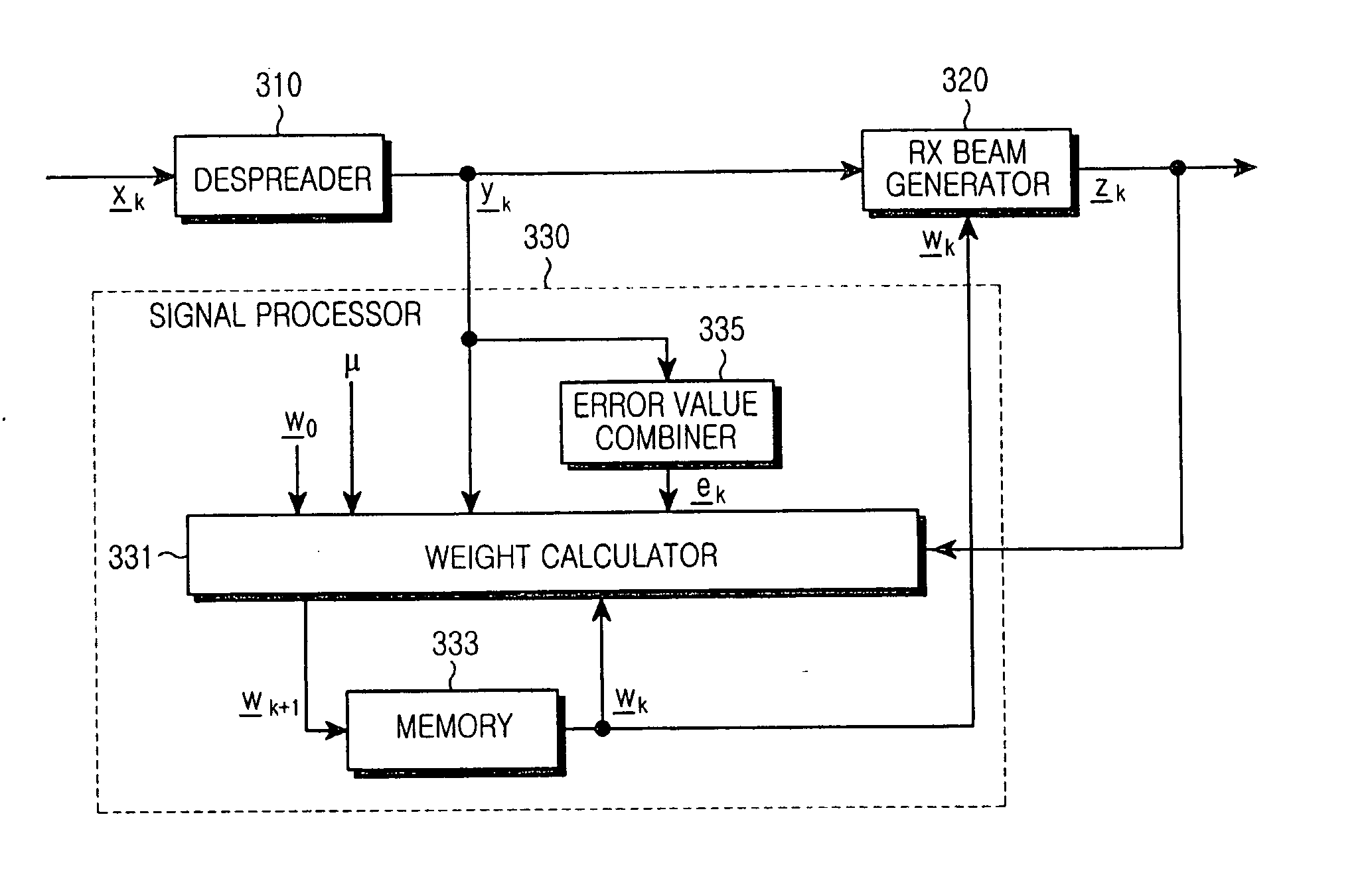
A mobile communication system receives a despread signal of a reception signal, and determines a first error value by using a first scheme at a timing point, and a second error value by using a second scheme different from the first scheme at the timing point, and determines a first scheme application weight according to a difference between the first error value and the second error value, and a second scheme application weight according to the difference between the first error value and the second error value, and generates a third error value using a scheme that combines the first scheme to which the first scheme application weight is applied and the second scheme to which the second scheme application weight is applied, and determines a reception beam weight using the despread reception signal, the third error value, and an output signal generated by applying the reception beam to the despread reception signal, wherein the reception beam weight is used for generating the reception beam.

Description

PRIORITY This application claims priority under 35 U.S.C. § 119 to an application entitled “Apparatus and Method for Receiving Data in a Mobile Communication System Using An Adaptive Antenna Array” filed in the Korean Intellectual Property Office on Jul. 16, 2003 and assigned Serial No. 2003-48898, the contents of which are incorporated herein by reference. BACKGROUND OF THE INVENTION 1. Field of the Invention The present invention relates generally to an apparatus and method for receiving data in a mobile communication system using an Adaptive Antenna Array (AAA) scheme, and in particular, to an apparatus and method for receiving data using an adaptive reception beam weight generation scheme. 2. Description of the Related Art A “next generation mobile communication system” has evolved into a packet service communication system that transmits burst packet data to a plurality of mobile stations (MSs). The packet service communication system is designed to transmit mass data. Suc...

Claims


Application Information

Patent Timeline
IPC IPC(8): H04B1/707H04B7/02H04B1/712H04B7/08H04B7/10H04J11/00H04W16/28H04W28/18
CPCH04B7/086H04B7/0854H04B7/02
Inventor CHAE, CHAN-BYOUNGSUH, CHANG-HODANIEL, KATZ MARCOSYOON, SEOK-HYUNKIM, BYOUNG-YUN
Owner SAMSUNG ELECTRONICS CO LTD
Learn More