
Apparatus and method for portioning flowable materials

a flowable material and apparatus technology, applied in the field of proportioning apparatus and a method for portioning flowable materials, can solve the problem of prohibitively high mechanical and hydraulic costs

Active Publication Date: 2005-01-20
AZZAR JAMES DOUGLAS
View PDF11 Cites 49 Cited by
  • Summary
  • Abstract
  • Description
  • Claims
  • Application Information

AI Technical Summary

Benefits of technology

"The patent describes an apparatus for portioning flowable materials and a method for using it. The apparatus includes a mold with two cavities, a first removal means for removing material from the first cavity, a second removal means for removing material from the second cavity, and a means for positioning the mold at different positions. The apparatus can be used in a portioning machine to process materials and transport them. The technical effects of the patent include improved efficiency in portioning flowable materials and improved control over the movement of the materials during processing."

Problems solved by technology

To increase the amount of knockout strokes, however, prohibitively high mechanical and hydraulic costs are required.

Method used


Image

  • Apparatus and method for portioning flowable materials
  • Apparatus and method for portioning flowable materials
  • Apparatus and method for portioning flowable materials

Examples


Embodiment Construction

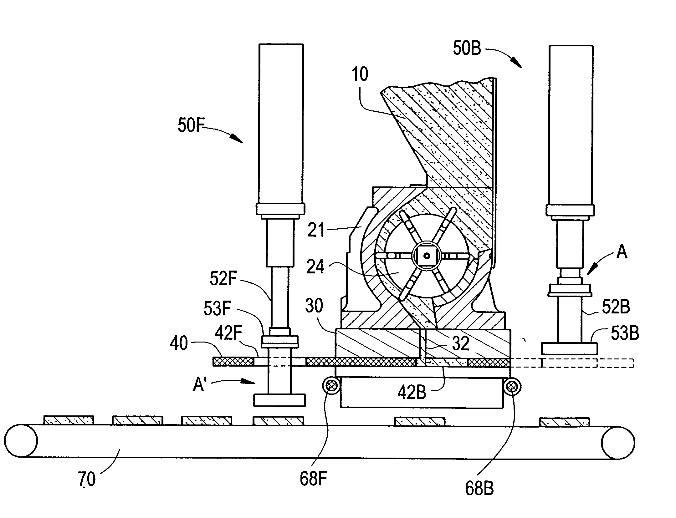
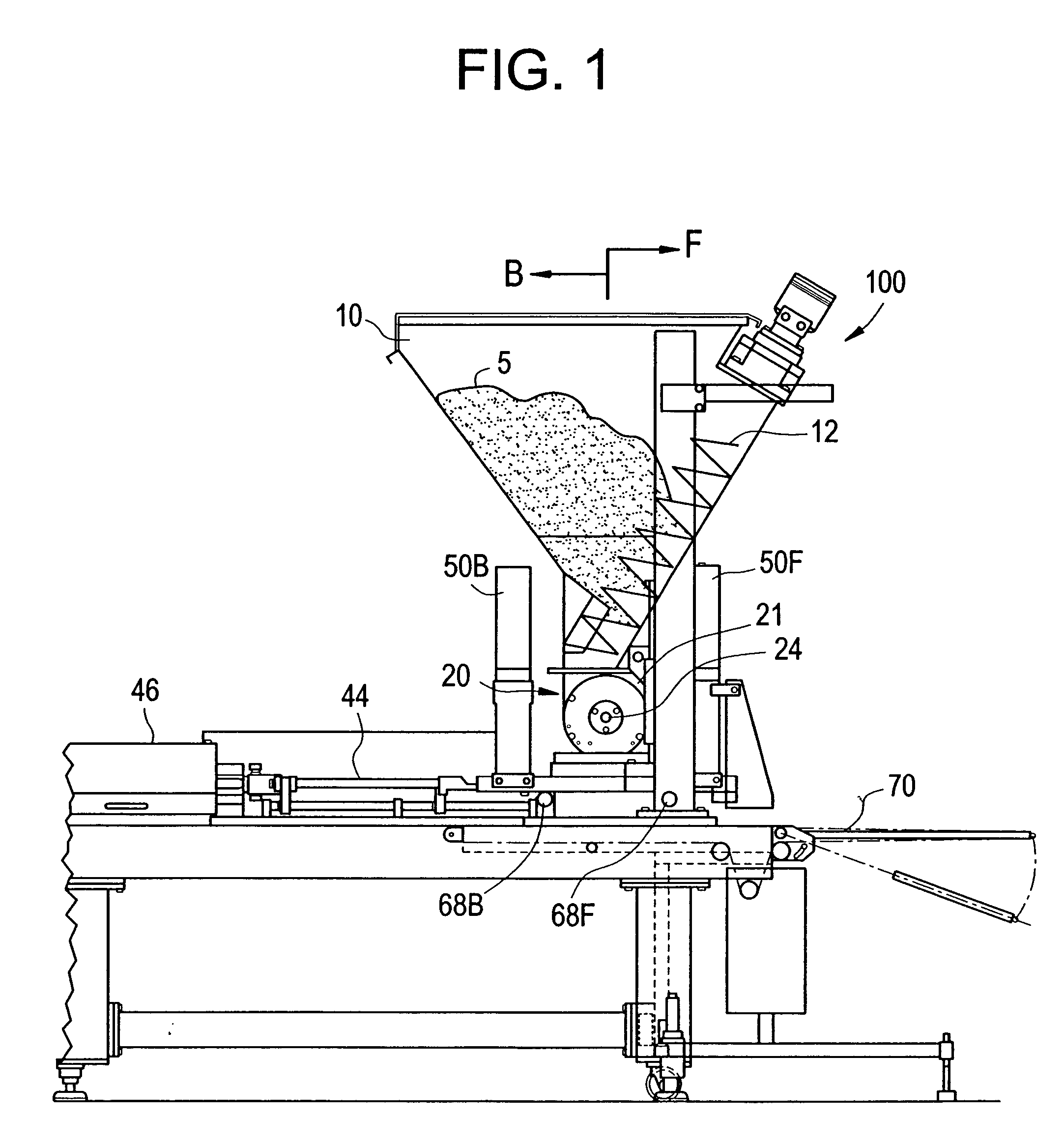
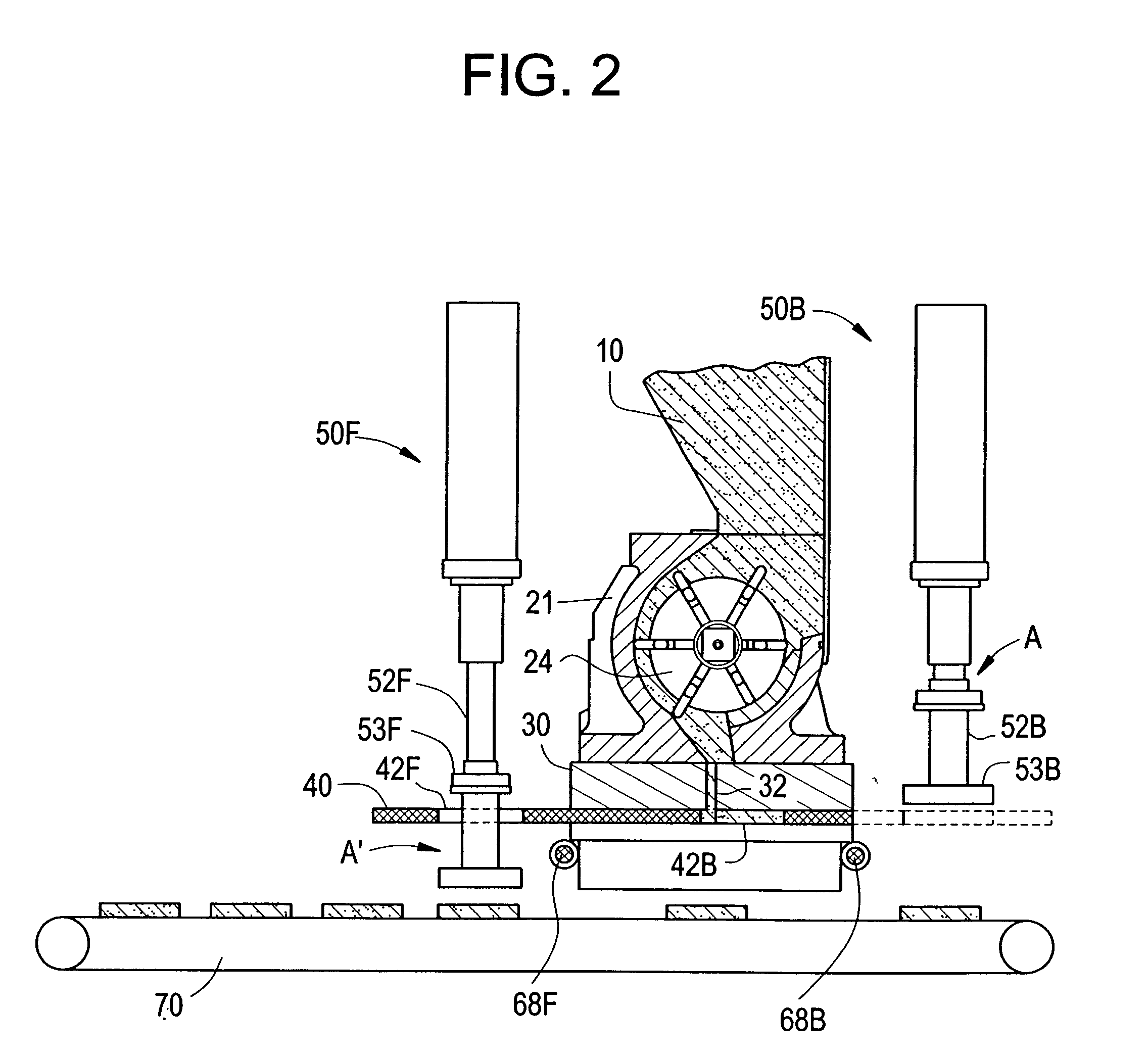
[0021] An exemplary embodiment will now be described with reference to FIGS. 1-3. A side view of a portioning apparatus 100 is shown in FIG. 1, a cross sectional view is shown in FIG. 2, and a smaller cross sectional view is shown in FIG. 3. In FIG. 1, the portioning apparatus 100 includes a front F and a back B, and a supply hopper 10 into which flowable material 5 such as flaked, shredded, or ground meat, fish, chicken, pork, potatoes, dough, etc., is received. Inside the supply hopper 10, there is a plurality of augers 12 leading down toward the bottom of the supply hopper 10 to a rotor assembly 20. Below the rotor assembly 20, there is a fill plate 30 with a fill slot 32 (FIG. 2). The size and positioning of the fill slot 32 varies with the type and size of the flowable material.

[0022] Underneath the fill plate 30, there is a mold plate 40 with a front mold cavity 42F and back mold cavity 42B, generally corresponding to the front F and the back B of the portioning apparatus 100...


PUM

PropertyMeasurementUnit
sizeaaaaaaaaaa
heightaaaaaaaaaa
mechanicalaaaaaaaaaa

Abstract

The invention relates to a portioning apparatus and a method. The apparatus includes a hopper and augers to push flowable material to a rotor. Retractable vanes on the rotor push the flowable material toward a fill slot as the rotor rotates. Below the fill slot, there is a mold plate with front and back mold cavities. In a front fill position, the mold plate is positioned so the front mold cavities are filled with flowable material from the fill slot while flowable material in the back mold cavities are pushed out by back knockouts. In a back fill position, the flowable material in the front mold cavities are pushed out by front knockouts while the back mold cavities are filled with flowable material from the fill slot. The mold plate reciprocatively oscillates between the front fill position and the back fill position for high output of portioned material.

Description

BACKGROUND OF THE INVENTION [0001] 1. Field of the Invention [0002] This invention relates to a portioning apparatus and a method for portioning flowable materials. More particularly, the invention relates to a machine for the portioning of flowable materials, such as flowable food, and a method for the same. [0003] 2. Description of the Related Art [0004] In certain industries, such as the food processing industry, portioning machines are used to portion flowable products. Flowable products include meat patties, flaked or shredded meat, fish, chicken, etc. In a portioning machine, there is a supply hopper which is fed with flowable material. An auger pushes the flowable material out a small opening to fill a mold. In the case of hamburger patties, the molds have a hollow flat cylindrical cavity in which the hamburger meat is filled. After the cavity is filled, the mold is moved underneath a knockout which knocks out the hamburger meat in the cavity to a conveyor belt below, in a kn...

Claims


Application Information

Patent Timeline
Patent Type & Authority Applications(United States)
IPC IPC(8): A22C7/00A23P1/10G01F11/16G01F11/30G01F13/00
CPCA22C7/00A23P1/105G01F13/005G01F11/30G01F13/003G01F11/16A23P30/10
Inventor AZZAR, JAMES DOUGLAS
Owner AZZAR JAMES DOUGLAS
Learn More