
Method and apparatus for testing an electronic device

Inactive Publication Date: 2005-01-20
HEWLETT PACKARD DEV CO LP
View PDF11 Cites 37 Cited by
  • Summary
  • Abstract
  • Description
  • Claims
  • Application Information

AI Technical Summary

Problems solved by technology

As electronic devices such as Application Specific Integrated Circuits (ASICs), microprocessors, etc. have become more complex, the cost and difficulty of testing such devices has increased.
However, some pins may not be testable.
However, it may not be cost effective to put boundary scan logic into every PCI card of the computer system.
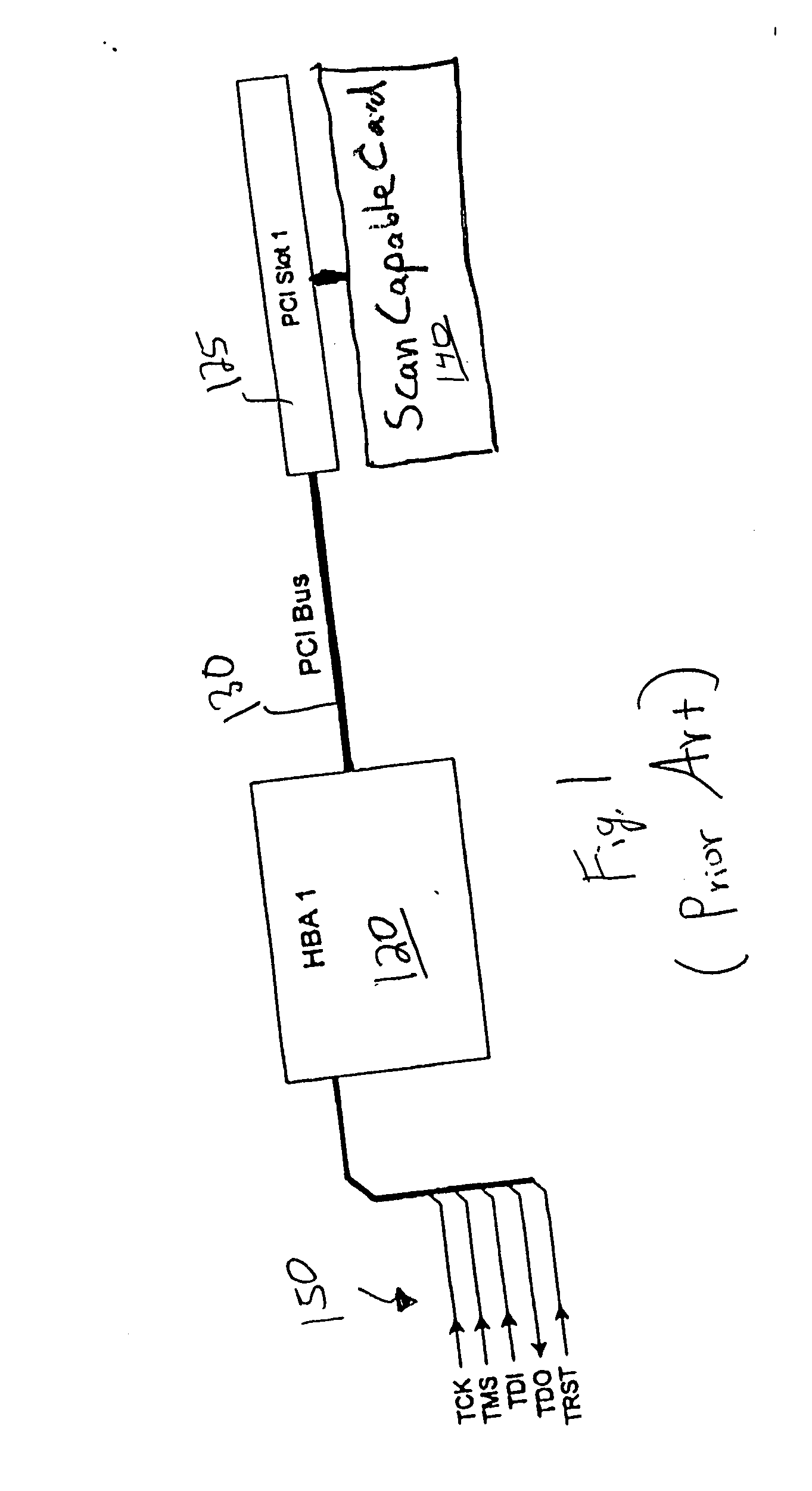
Unfortunately, the edge connectors of the test scan capable card wear with each insertion / removal from a PCI slot 125.
Typically, the edge connectors last only about 100 insertions before the wear to the connector is sufficient to cause intermittent connection problems.
Such intermittent connection problems will falsely cause the DUT to fail the test.
Replacement of the test scan capable card is expensive.
However, not all slots to be tested require JTAG support per an accepted industry standard.
However, the slots without support for JTAG cannot be tested by the technique illustrated in FIG. 1.
Therefore, a less convenient method of testing must be used if the slot is to be tested.
Thus, one problem with some conventional methods of and devices for testing an electronic device is the expense incurred in placing boundary scan logic into a device's card for testing the electronic device external to the card itself.
Alternatively, a boundary scan compliant card that is not a part of the electronic device can be used for testing, but such cards are expensive and their connectors wear out rapidly, which adds further to the testing expense.
Moreover, if the test boundary scan card is not replaced before it goes intermittent, the test of the DUT is inaccurate.
A still further problem is the expense incurred in running boundary scan traces to every slot in an electronic device to support a scan test of each slot.

Method used


Image

  • Method and apparatus for testing an electronic device
  • Method and apparatus for testing an electronic device
  • Method and apparatus for testing an electronic device

Examples


Embodiment Construction

[0018] In the following detailed description of embodiments of the present invention, a method of and an apparatus for testing an electronic device, numerous specific details are set forth in order to provide a thorough understanding of the present invention. However, embodiments of the present invention may be practiced without these specific details or by using alternative elements or methods. In other instances well known methods, procedures, components, and circuits have not been described in detail as not to unnecessarily obscure aspects of the present invention.

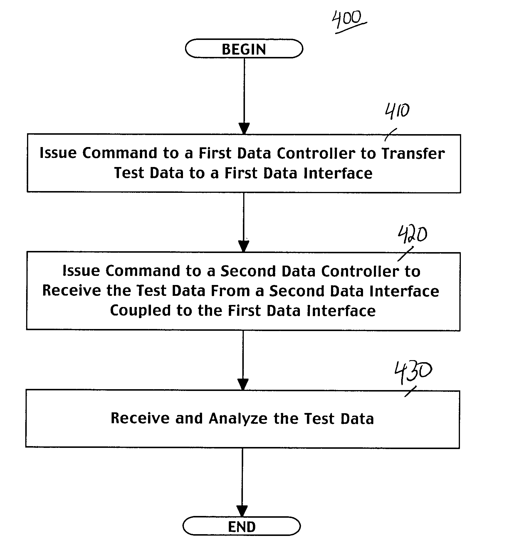
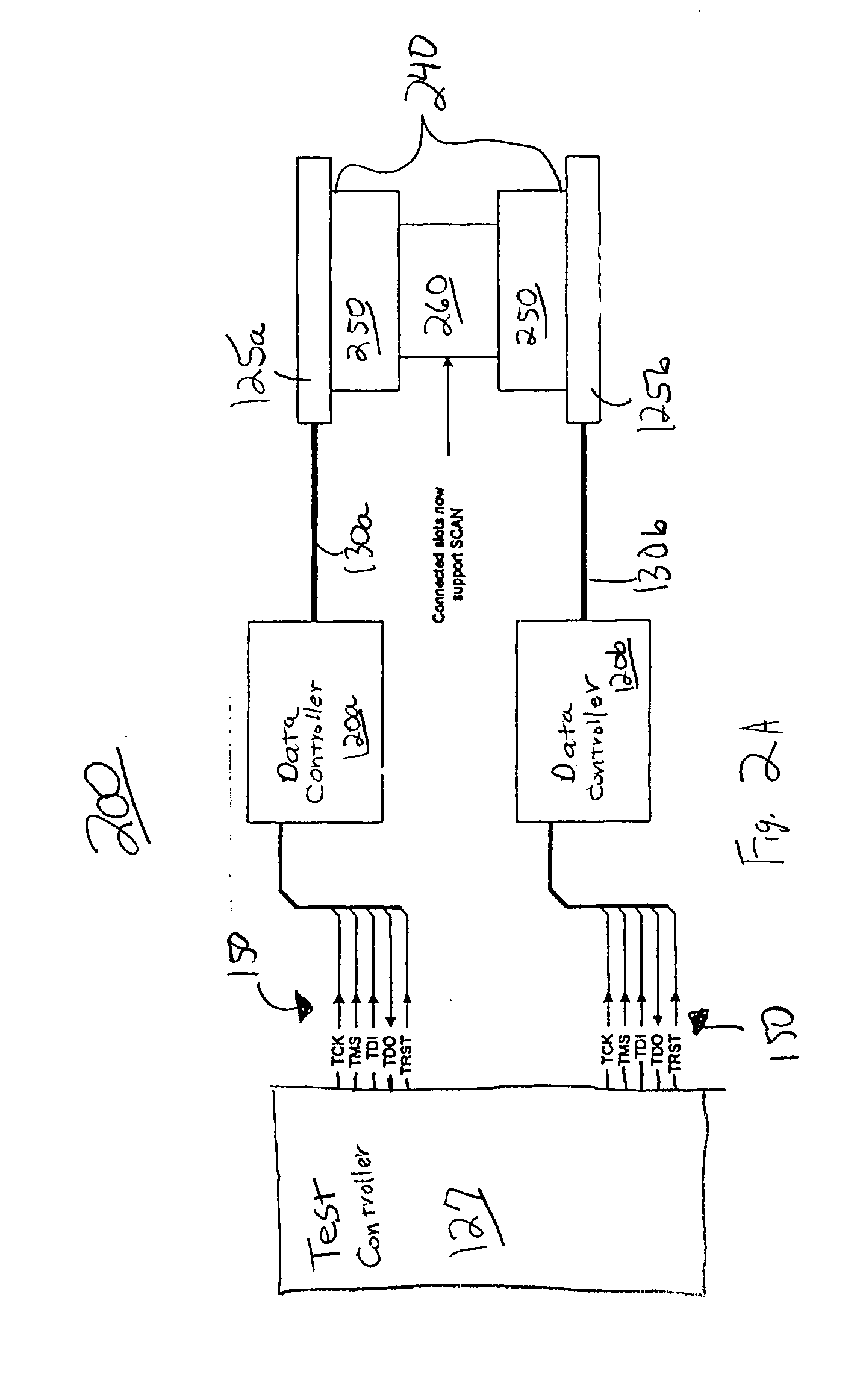
[0019] Embodiments of the present invention provide a way to test an electronic device by bridging two data interfaces of the electronic device. The two data interfaces are not typically connected during normal operation of the electronic device. The electronic device has a first scan capable component that is able to drive scan data to one of the data interfaces and a second scan capable component that is able to rece...


PUM


Abstract

A method of testing an electronic device. A test pattern is transferred between a first data controller coupled to a first data interface and a second data controller coupled to a second data interface via an element coupling the first and second data interfaces. The test pattern is received and examined.

Description

TECHNICAL FIELD [0001] The present invention relates to the field of testing electronic devices. Specifically, embodiments of the present invention relate to methods and devices for testing an electronic device by using a bridge between multiple data interfaces of the electronic device. BACKGROUND ART [0002] As electronic devices such as Application Specific Integrated Circuits (ASICs), microprocessors, etc. have become more complex, the cost and difficulty of testing such devices has increased. Boundary scan methodology was developed as a way to simplify the testing of an electronic device, referred to herein as a device under test (DUT), that complies with boundary scan requirements. Boundary scan methodology comprises the use of a scan chain or loop to transfer test data from a test controller to at least one DUT and back to the test controller. Special hardware, such as boundary cells and dedicated pins, may be added to a DUT to make it boundary scan compliant. The boundary cell...

Claims


Application Information

Patent Timeline
IPC IPC(8): G01R31/3185G06F11/267
CPCG06F11/2236G01R31/318533
Inventor SOMERVILL, KEVINCHAU, ANDREWDOBBS, ROBERT WILLIAM
Owner HEWLETT PACKARD DEV CO LP
Learn More