
Devices for monitoring digital video signals and associated methods and systems

Inactive Publication Date: 2005-01-20
MORGAN STANLEY +1
View PDF22 Cites 50 Cited by
  • Summary
  • Abstract
  • Description
  • Claims
  • Application Information

AI Technical Summary

Benefits of technology

An advantage of the present invention is that it leverages the proliferation of visual display formats used to convey pixel data between a graphics controller in a computer of a local computer station and a display controller in a display unit of the local computer station. A monitoring system includes devices that can capture, encrypt, compress, convert, and transmit the pixel data in a data transfer protocol format (e.g., IP) from the local computer station to a remote computer station. The monitoring system can make use of a preexisting network so that the monitoring system can be implemented inexpensively and with minimal burden. A device is also provided that enables a network, having components with compatible visual display formats, to be configured to act as a monitoring system.
is that it leverages the proliferation of visual display formats used to convey pixel data between a graphics controller in a computer of a local computer station and a display controller in a display unit of the local computer station. A monitoring system includes devices that can capture, encrypt, compress, convert, and transmit the pixel data in a data transfer protocol format (e.g., IP) from the local computer station to a remote computer station. The monitoring system can make use of a preexisting network so that the monitoring system can be implemented inexpensively and with minimal burden. A device is also provided that enables a network, having components with compatible visual display formats, to be configured to act as a monitoring system.
The accompanying drawings, which are incorporated herein and form part of the specification, illustrate the present invention and, together with the description, further serve to explain the principles of the invention and to enable a person skilled in the pertinent art to make and use the invention.
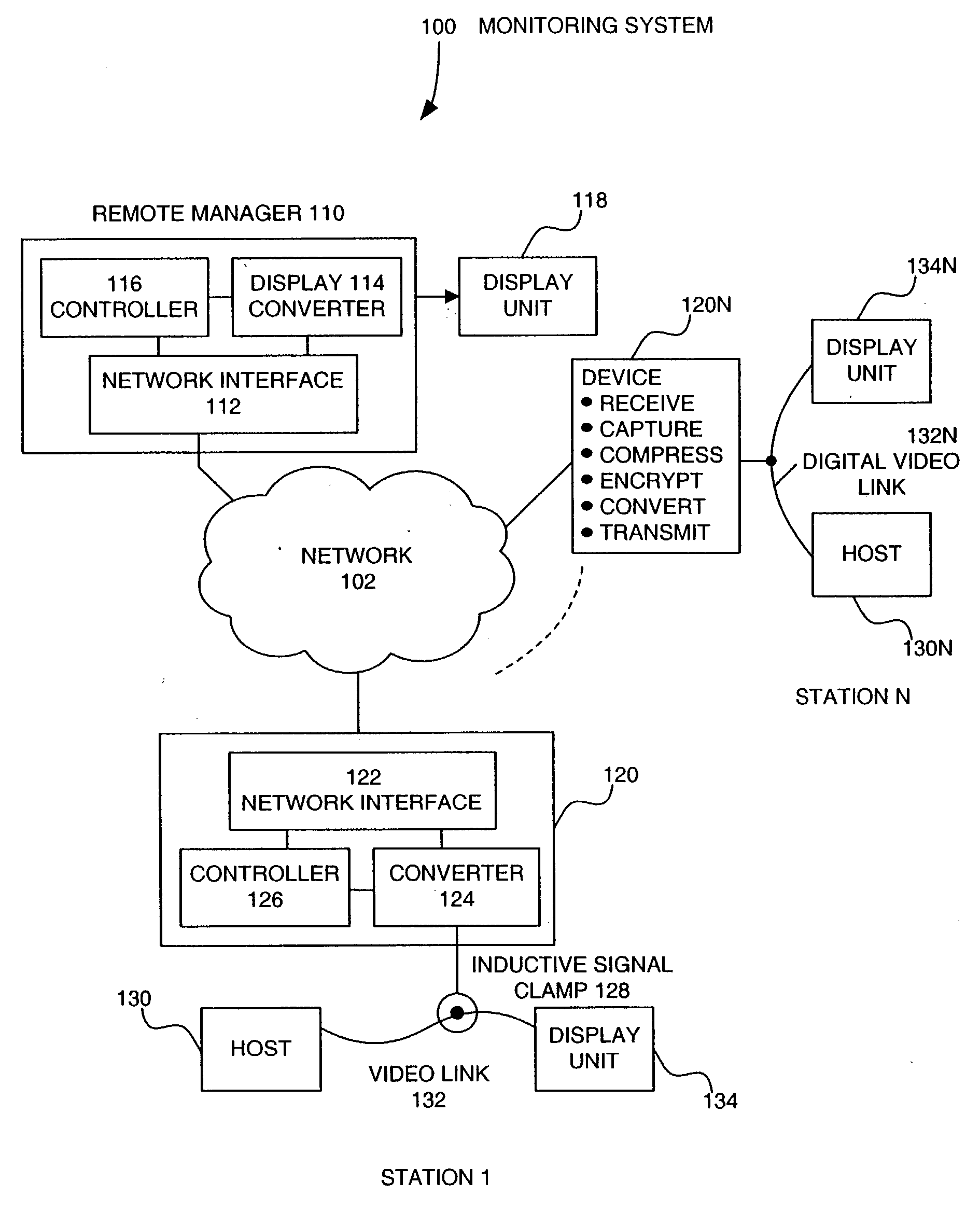
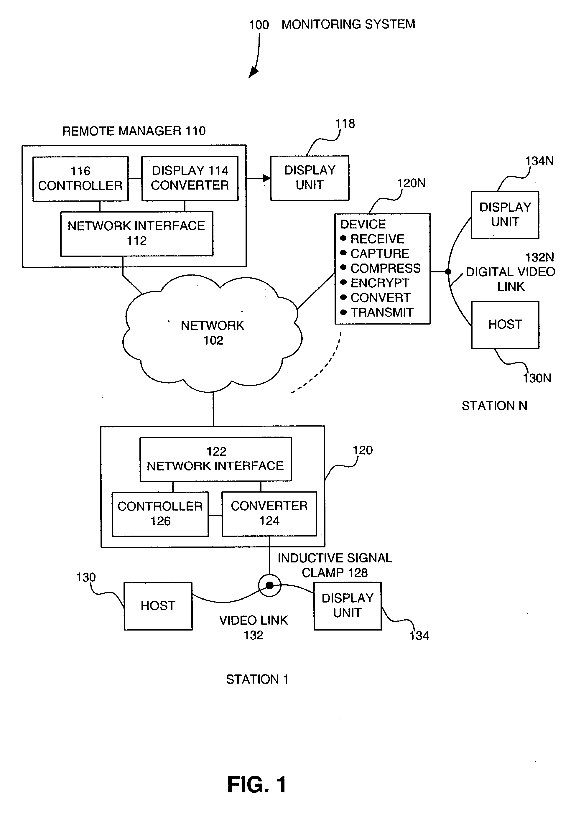
FIG. 1 shows a monitoring system configured in the manner of the present invention.
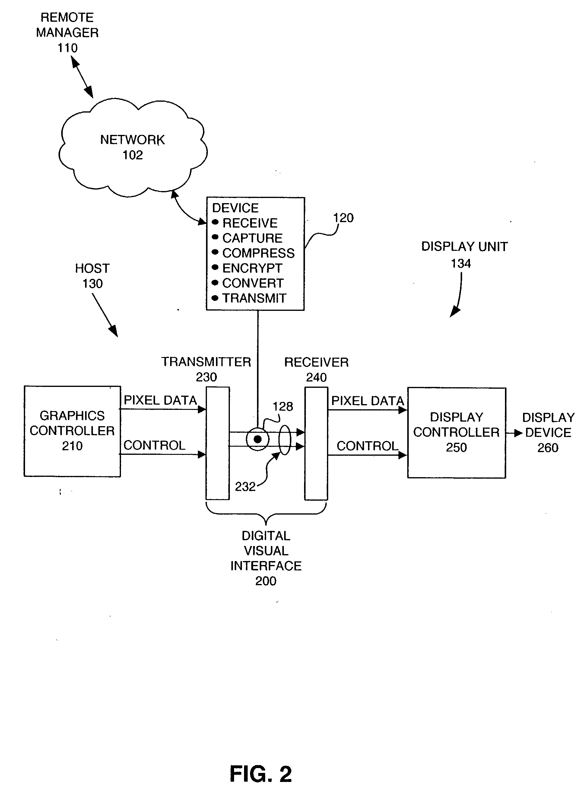
FIG. 2 highlights how the present invention interacts with a digital video link, such as Digital Video Interface.
FIG. 3 depicts an exemplary network configured as a monitoring system in the manner of the present invention.

Problems solved by technology

Implementations of monitoring systems, however, have drawbacks.
The video switching network is limited in that it needs to be customized for a specific application.
Such customization and compatibility requirements do not allow a monitoring system to be implemented across heterogeneous display units of varying type and vendor.
This can increase the cost of implementing a monitoring system, especially if more inexpensive or legacy display units or computers cannot be accommodated.

Method used


Image

  • Devices for monitoring digital video signals and associated methods and systems
  • Devices for monitoring digital video signals and associated methods and systems
  • Devices for monitoring digital video signals and associated methods and systems

Examples


Embodiment Construction

Table of Contents Overview Terminology Monitoring System Method System Computer Program Product Interface Card Connectors Conclusion

Overview

The present invention relates to devices for monitoring digital video signals and associated monitoring methods and systems. The present invention uses network technology and a digital display interface (e.g., Digital Visual Interface Transition Minimized Differential Signaling (DVI TMDS)) to produce a monitoring system. Where a network connects a local computer station to a remote computer station, and a computer of the local computer station transmits data in a visual display (pixel) format to a display unit of the local computer station, the present invention provides a device that can form the data into a data transfer protocol format (e.g., Internet Protocol (IP)) and transmit the formed data through the network to the remote computer station for display on a display unit of the remote computer station. Thus, the present inven...


PUM


Abstract

Data related to information displayed on a local display unit is formed into a data transfer protocol format (e.g., Internet Protocol (IP)). Typically, the data is captured before it is formed into the data transfer protocol format. The formed data is transmitted through a network. The transmitted data is received at a remote computer station. The received data is converted to a visual display (pixel) format (e.g., Digital Visual Interface (DVI)). Typically, the converted data is stored in a frame buffer of the remote computer station. The converted data is displayed on a remote display unit of the remote computer station.

Description

BACKGROUND OF THE INVENTION 1. Field of the Invention The present invention relates to digital video monitoring and display. 2. Background Art Monitoring systems are used to monitor multiple display units. For example, a monitoring system allows a supervisor or a commander to monitor activity across a number of display units. Some monitoring systems also allow a supervisor or a commander to select and place individual screens or portions of screens on a large multi-person viewable display system. Monitoring systems are used in a variety of applications including, but not limited to, security, surveillance, education, battlefield command and control, observation of manufacturing or repair processes (particularly in harsh environments), teleconferencing, air traffic control, television program production, control of space vehicles, observation of securities exchange activities, and endoscopic surgery. Implementations of monitoring systems, however, have drawbacks. One approach is...

Claims


Application Information

Patent Timeline
IPC IPC(8): H04L29/06H04N7/18
CPCG06F3/1454G08B13/19634G08B13/19667G08B13/19682H04L67/38G09G5/006H04L29/06H04N7/181G08B13/19693H04L67/131H04L9/40
Inventor FORAN, JAMES L.
Owner MORGAN STANLEY
Learn More