Accelerating method, optomedical device, and optomedical system

a technology of optomedical devices and neurotransmitters, applied in the field of accelerating methods, optomedical devices, optomedical systems, can solve the problems of adverse effects on the human body, the disadvantage of comparatively intensive light beams directed to the retina for the secretion of neurotransmitters,

Active Publication Date: 2018-08-07
TERUMO KK
View PDF6 Cites 0 Cited by
  • Summary
  • Abstract
  • Description
  • Claims
  • Application Information

AI Technical Summary

Benefits of technology

[0009]In light of the foregoing, certain embodiments of the present invention are intended to provide a method for adequately accelerating the release of neurotransmitters, an optomedical device, and an optomedical system which will be applied to the human body with a minimum of burden thereon.
[0010]According to one embodiment, an accelerating method includes a step of photoirradiation to accelerate the release of neurotransmitters, the step being accomplished by radiating light within a cerebral blood vessel. This step stimulates the photoreceptor existing in the brain, thereby adequately accelerating the release of neurotransmitters. The acceleration in this manner imposes a less amount of burden on the body than that by irradiating the retina with light.
[0011]In one aspect, the step of photoirradiation is accomplished by directing the light radiated from within the cerebral blood vessel to the pineal body. Light radiation in this manner efficiently accelerates the release of neurotransmitters.

Problems solved by technology

Unfortunately, the above-mentioned medical device has the disadvantage of needing comparatively intensive light beams directed to the retina for the secretion of neurotransmitters such as serotonin.
This would cause an adverse effect on the human body.

Method used


Image

  • Accelerating method, optomedical device, and optomedical system
  • Accelerating method, optomedical device, and optomedical system
  • Accelerating method, optomedical device, and optomedical system

Examples


first embodiment

The First Embodiment

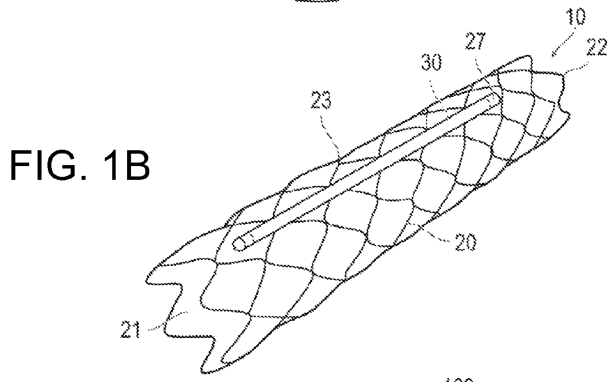
[0042]FIGS. 1A-1C are diagrams illustrating the optomedical device and optomedical system pertaining to the first embodiment. FIGS. 2A and 2B are diagrams illustrating the structure of the human brain to which the optomedical device is applied. FIGS. 3A and 3B are diagrams illustrating the optomedical device and optomedical system being used in a typical way. FIGS. 4 to 6 are diagrams illustrating the configuration and function of the optomedical device and optomedical system.

[0043]As shown in FIG. 1B, FIGS. 3A and 3B, and FIG. 4, an optomedical device 10 includes a main body 20 to be inserted into a cerebral blood vessel 300, a light emitting unit 30 attached to the main body 20 which radiates light to accelerate the release of neurotransmitters, and a control unit 41 which controls the action of the light emitting unit 30.

[0044]The optomedical device 10 is intended to radiate light within the cerebral blood vessel 300 of a subject (living body), thereby acceler...

second embodiment

The Second Embodiment

[0140]The following describes the optomedical system pertaining to a second embodiment of the present invention. The optomedical systems pertaining to the first and second embodiments are similar to each other in their structure except for some aspects. The description of their common structure is omitted.

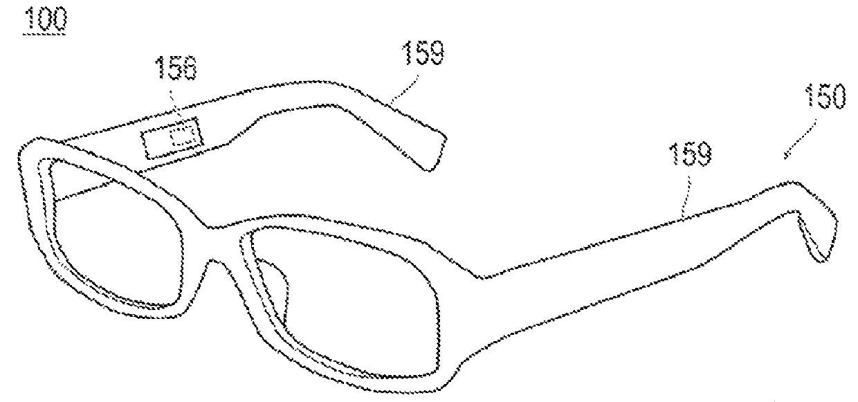
[0141]The optomedical system 100 according to the first embodiment mentioned above is constructed such that the operating device 150 has the detecting unit 156, which detects the subject's physiological state, and the determination unit 154, which allows the optomedical device 10 to work according to the result of determination, whereas an operating device 550 of an optomedical system 500 pertaining to the second embodiment lacks the detecting unit and the determination unit as shown in FIG. 7. Thus the optomedical system 500 does not detect automatically the subject's physiological state during its operation and hence does not perform action control according ...

third embodiment

The Third Embodiment

[0144]The following describes the optomedical system pertaining to a third embodiment of the present invention. The optomedical systems pertaining to the first, second, and third embodiments are similar to one another in their structure except for some aspects. The description of their common structure is omitted.

[0145]As shown in FIG. 8, an optomedical system 600 pertaining to the third embodiment is equipped with an operating device 650 which has a detecting unit 656. The detecting unit 656 detects the sleeping state as one of the physiological states of the subject.

[0146]The detecting unit 656 may be any known sensor (such as CMOS sensor and CCD sensor) which is capable of observing the subject's eye movement.

[0147]If the detecting unit 656 detects that the subject is keeping his eye closed for a certain period of time, the operating device 650 determines that the subject is sleeping. In response to the result of the determination, the operating device 650 tra...


PUM


Abstract

A method for accelerating the release of neurotransmitters includes a step of radiating light from within a cerebral blood vessel to accelerate the release of the neurotransmitters. An optomedical device includes a main body configured to be introduced into a cerebral blood vessel; a light emitting unit arranged on the main body, the light emitting unit configured to radiate light to accelerate the release of neurotransmitters; and a control unit configured to control a light emitting action of the light emitting unit.

Description

CROSS-REFERENCE TO RELATED APPLICATIONS[0001]This application claims priority to Japanese Patent Application No. 2013-237208, filed on Nov. 15, 2013, which is hereby incorporated by reference in its entirety.BACKGROUND[0002]Technical Field[0003]The present disclosure relates to a method for accelerating the release of neurotransmitters, an optomedical device, and an optomedical system.[0004]Background Art[0005]It is a well-known fact that a variety of neurotransmitters secreted in the human brain greatly affect the human's mental state and physiological state. It is believed, for example, that the amount of secretion of neurotransmitters is closely related with the onset of such mental diseases as depression, panic disorder, and schizophrenia. Among neurotransmitters most influential on the mental state are those of monoamine type such as dopamine, serotonin, and noradrenaline.[0006]For example, depression is caused by a decrease in secretion of dopamine and ADHD (attention-deficit-...

Claims


Application Information

Patent Timeline
Patent Type & Authority Patents(United States)
IPC IPC(8): A61N5/06
CPCA61N5/0601A61N5/0622A61N2005/0663A61N2005/0627A61N2005/0661A61N2005/0602
Inventor NARITA, MAKOTO
Owner TERUMO KK
Why Eureka
Try Eureka