Workflow management apparatus and method
- Summary
- Abstract
- Description
- Claims
- Application Information
AI Technical Summary
Benefits of technology
Problems solved by technology
Method used
Image

Examples
first embodiment
[First Embodiment]
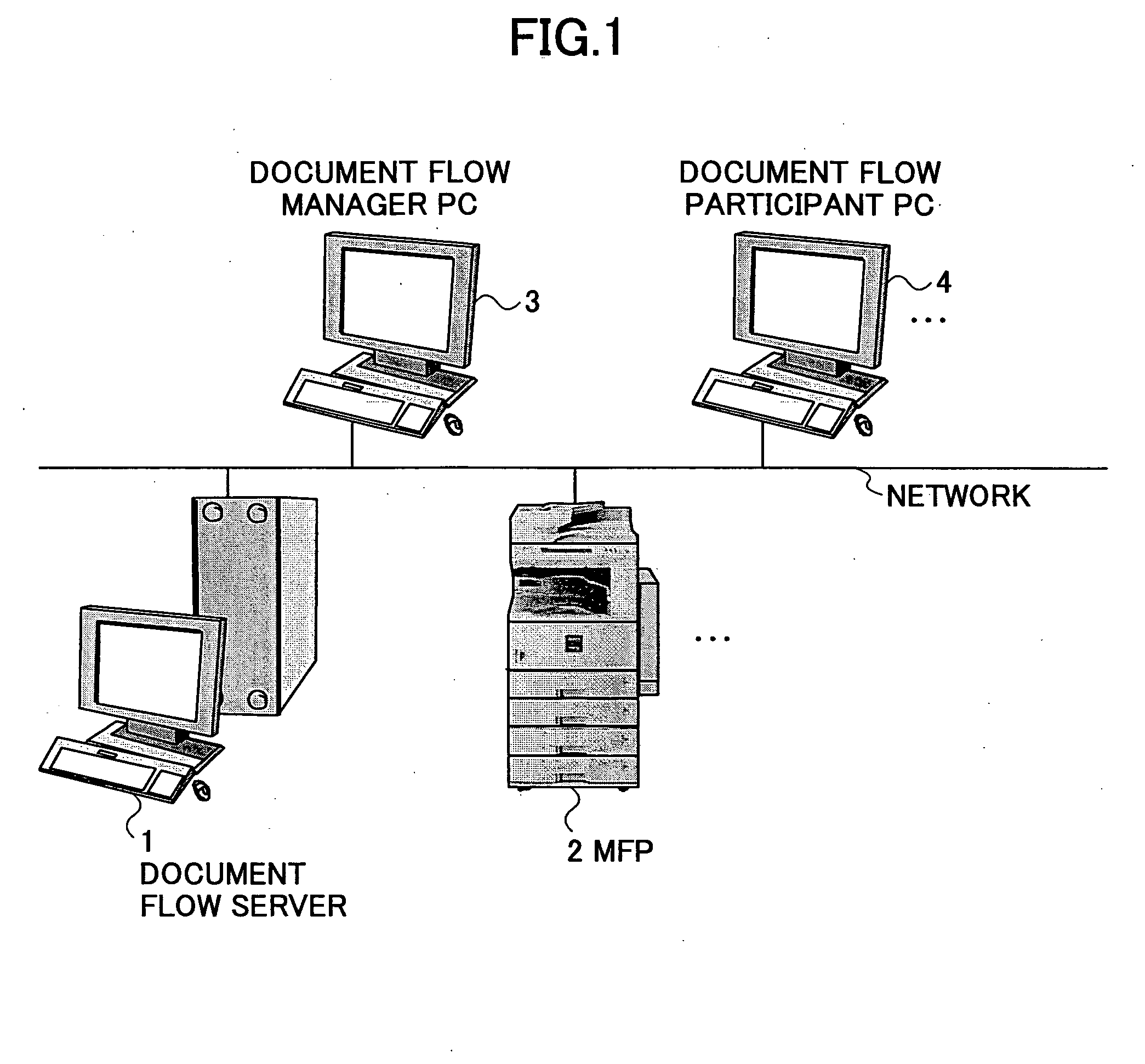
FIG. 1 is a concept diagram showing a document flow system according to a first embodiment of the present invention. As shown in FIG. 1, the document flow system includes a document flow server 1, at least one MFP 2, a document flow manager PC 3, and at least one document flow participant PC 4, which are connected via a network.
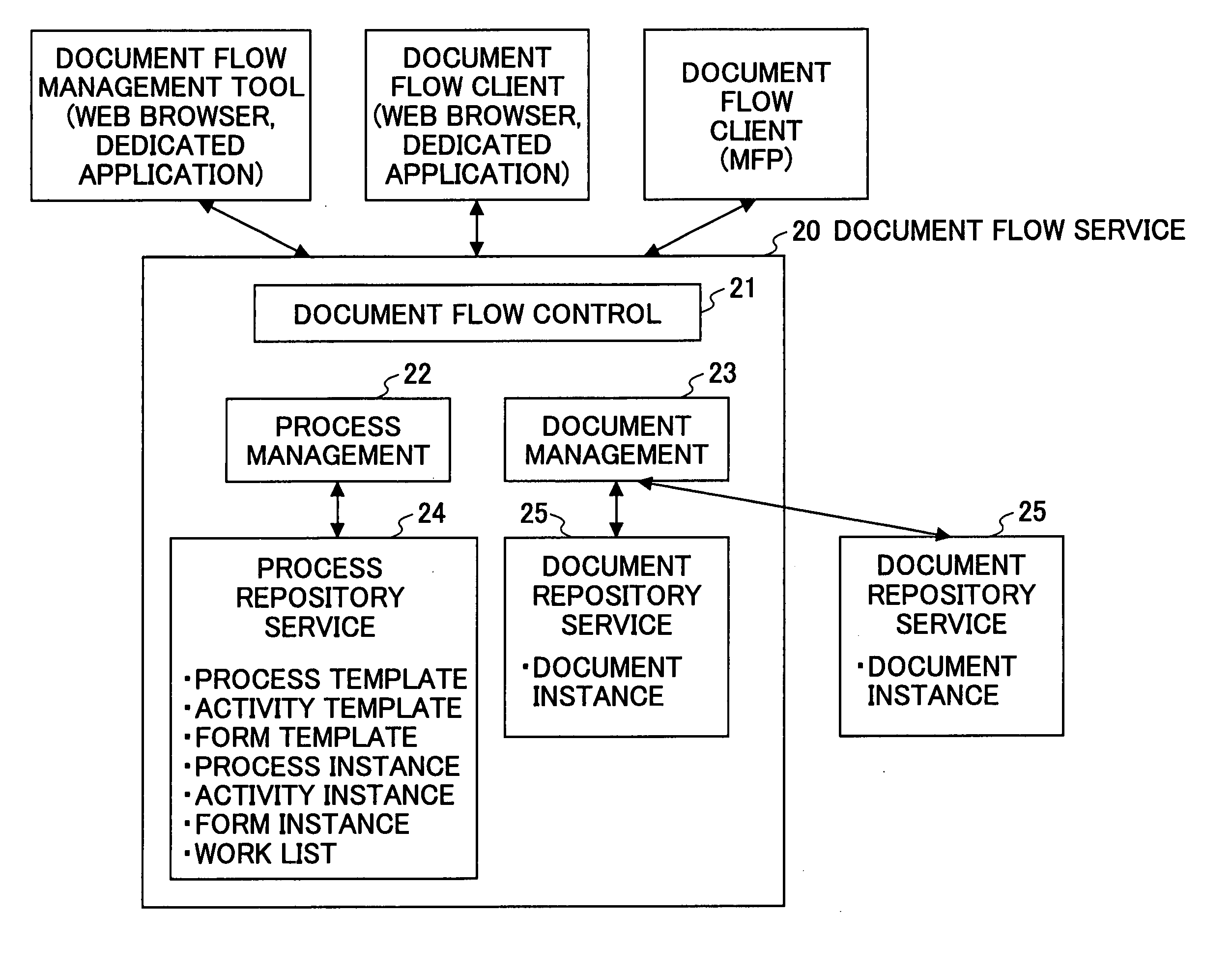
The document flow server 1 includes a below-described document flow service 20, which manages, for instance, a process and a document relating to a document flow.
The document flow system manager PC 3 includes a document flow management tool for a document flow manager. For instance, the document flow manager, using the document flow management tool, queries the document flow server 1 for the status of each process so as to manage the process and create the template of the process. The document flow management tool may be a Web browser or a dedicated application.
The document flow participant PC 4 includes a tool having a GUI used by a d...
second embodiment
[Second Embodiment]
In the first embodiment, the activity templates and / or the activity instances are included in the information item “sequence” as shown in, for instance, FIGS. 10, 11, 13, and 14. Alternatively, the activity templates and / or the activity instances may be provided outside the information item “sequence.” A description is given below, with reference to FIGS. 22 and 23, of the case where the activity templates and / or the activity instances are provided outside the information item “sequence.” In the second embodiment, the difference from the first embodiment is described.
FIG. 22 is a diagram for illustrating a configuration of the process template according to the second embodiment. In contrast to the process template shown in FIG. 10 of the first embodiment, the activity templates are provided outside the information item “sequence” in the process template shown in FIG. 22.
As shown in FIG. 22, an activity template may be provided outside the information item “seq...
third embodiment
[Third Embodiment]
In the above-described embodiments, as shown in FIG. 20 of the first embodiment, a process is started after selecting a document and obtaining a process template list. Alternatively, the document may be selected after obtaining the process template list and starting the process. A description is given below, with reference to FIG. 24, of the case of selecting a document after obtaining a process template list and starting a process. In the third embodiment, the differences from the first and second embodiments are described.
FIG. 24 is a sequence diagram of process starting according to the third embodiment.
Referring to FIG. 24, first, a document flow participant requests the document flow client to obtain a process template list. Then, in step S40 of FIG. 24, the document flow client, requested by the document flow participant to obtain a process template list, transmits a process template list obtaining request to the document flow service 20.
In step S41, re...
PUM
 Abstract
Description
Claims
Application Information