Automatically configuring a raster image processor

a raster image processor and automatic configuration technology, applied in the field of image processing, can solve the problems of substantially limited print shops, fast print job turn-around time, and substantial problem in techniqu

a raster image processor and automatic configuration technology, applied in the field of image processing, can solve the problems of substantially limited print shops, fast print job turn-around time, and substantial problem in techniqu

US20050015779A1Active Publication Date: 2005-01-20HEWLETT PACKARD DEV CO LP

Image

  • Automatically configuring a raster image processor
  • Automatically configuring a raster image processor
  • Automatically configuring a raster image processor

Examples


Embodiment Construction

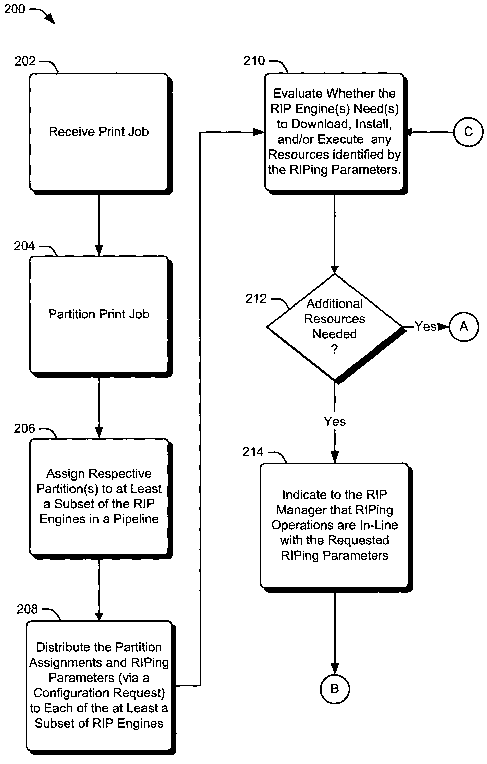
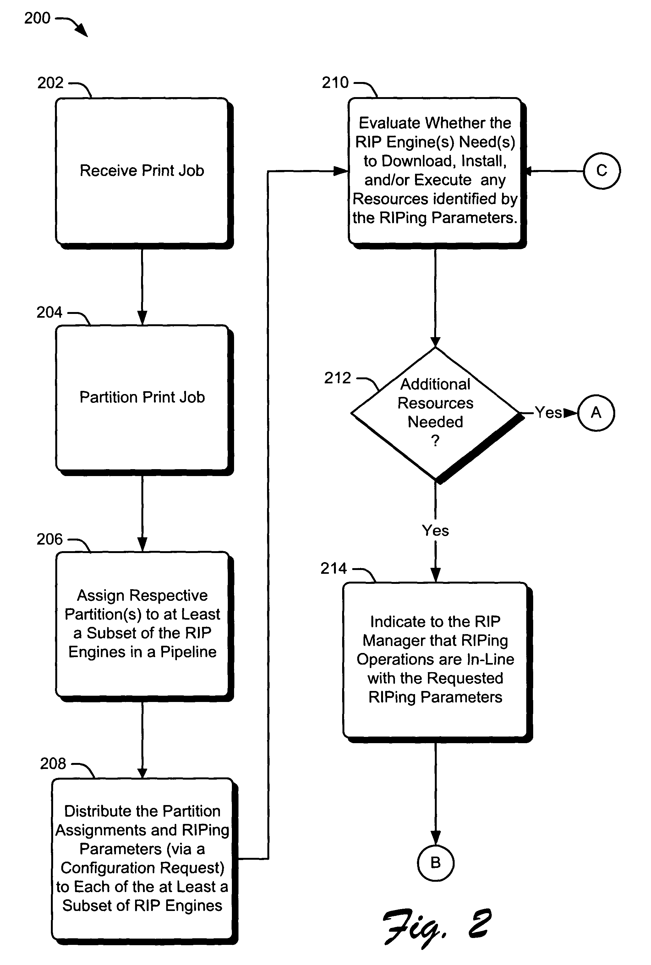
[0014] An Exemplary Operating Environment

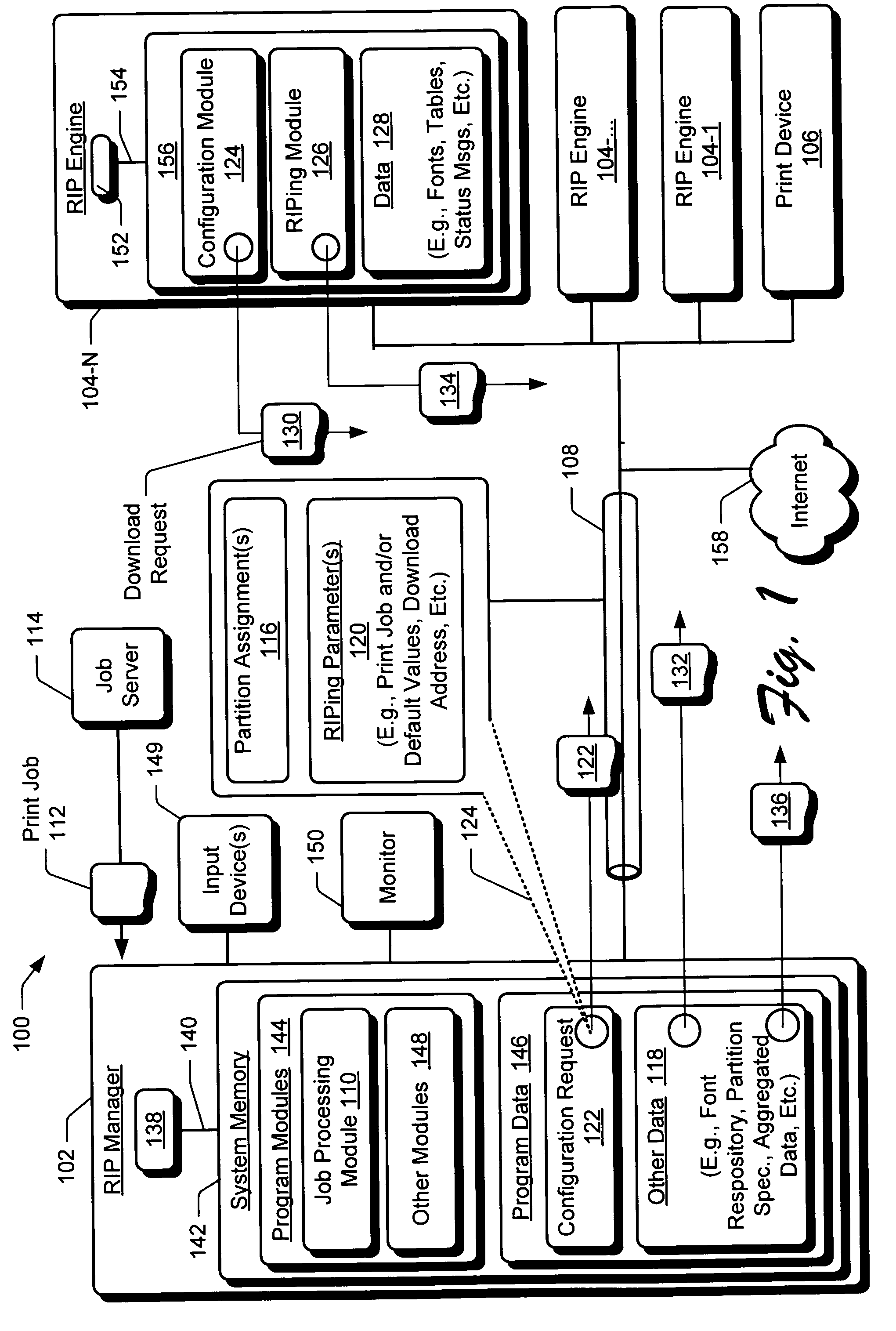
[0015] Turning to the drawings, wherein like reference numerals refer to like elements, the invention is illustrated as being implemented in a suitable computing environment. FIG. 1 is an exemplary suitable computing environment 100 within which systems, apparatuses and methods to configure a raster image processor (RIP) engine may be implemented. In particular, the system of FIG. 1 provides for cooperative image processing across heterogeneous RIP engines. Multiple RIP engines that respectively implement different RIPing algorithms / resources, etc., with respect to one another are often referred to as being ā€œheterogeneousā€ with respect to one another. Exemplary computing environment 100 is only one example of a suitable computing environment and is not intended to suggest any limitation as to the scope of use or functionality of systems and methods the described herein.

[0016] Although not required, the invention will be described in the gen...


PUM


Abstract

Systems and methods to configure a Raster Image Processor (RIP) are described. In one aspect, a networked computing environment includes a RIP manager coupled to at least one RIP engine. A print job is received. The RIP engine is requested to dynamically configure its RIPing operations when at least one of the RIP Engine's RIPing parameters is not congruent to a RIP manager supplied processing preference. Such dynamic configuration is requested in consideration of the RIP engine RIPing a particular portion of the print job.

Description

TECHNICAL FIELD [0001] The invention pertains to image processing. BACKGROUND [0002] In print shop environments, digital vector data is generally expressed in a Page Description Language (PDL) data format. Examples of PDLs include, Hewlett-Packard's Printer Control LanguageĀ® (PCL), Adobe's Portable Document FormatĀ® (PDF), or Adobe's PostScriptĀ® (PS). In print shop environments, digital image data are typically represented as JPEG, TIFF, and / or like data formats (such data formats can also be present in a print job). Prior to printing or otherwise presenting image data that is in any one of these digital data formats, vector data and image data must be rasterized. Rasterization or ā€œraster image processingā€ (RIPing) is the process of translating digital vector and image data into bit-mapped data or raster bits for rendering by a printer or display device. [0003] Efficient print job turn-around time is of paramount importance for successful print shop operations. In view of this, a pri...

Claims


Application Information

Patent Timeline
20 Jan 2005
Publication
US20050015779A1
IPC
G06F3/12; G06F9/46
CPC
G06F3/1204; G06F3/1215; G06F3/1285; G06F3/124; G06F3/1284; G06F3/123
Inventors
CHRISTIANSEN, ROBERT DOUGLAS