Disk player

Inactive Publication Date: 2005-01-20
FUNAI ELECTRIC CO LTD
View PDF4 Cites 6 Cited by
  • Summary
  • Abstract
  • Description
  • Claims
  • Application Information

AI Technical Summary

Benefits of technology

[0007] It is an object of the invention to provide a disk player achieving a reduction in cost and small-sized formation and enabling to move a tray forward and rearward linearly without inclining the tray.

Problems solved by technology

Further, the cabinet 1 needs to be longer than the tray 3 by an amount of a length L of the elastic plate 6 and therefore, there is also a difficulty of making the disk player large-sized.

Method used


Image

  • Disk player
  • Disk player
  • Disk player

Examples


Embodiment Construction

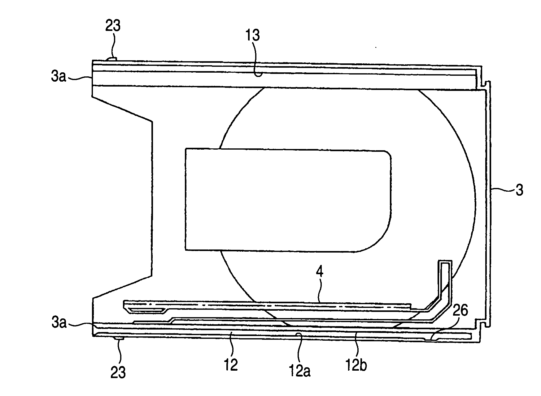
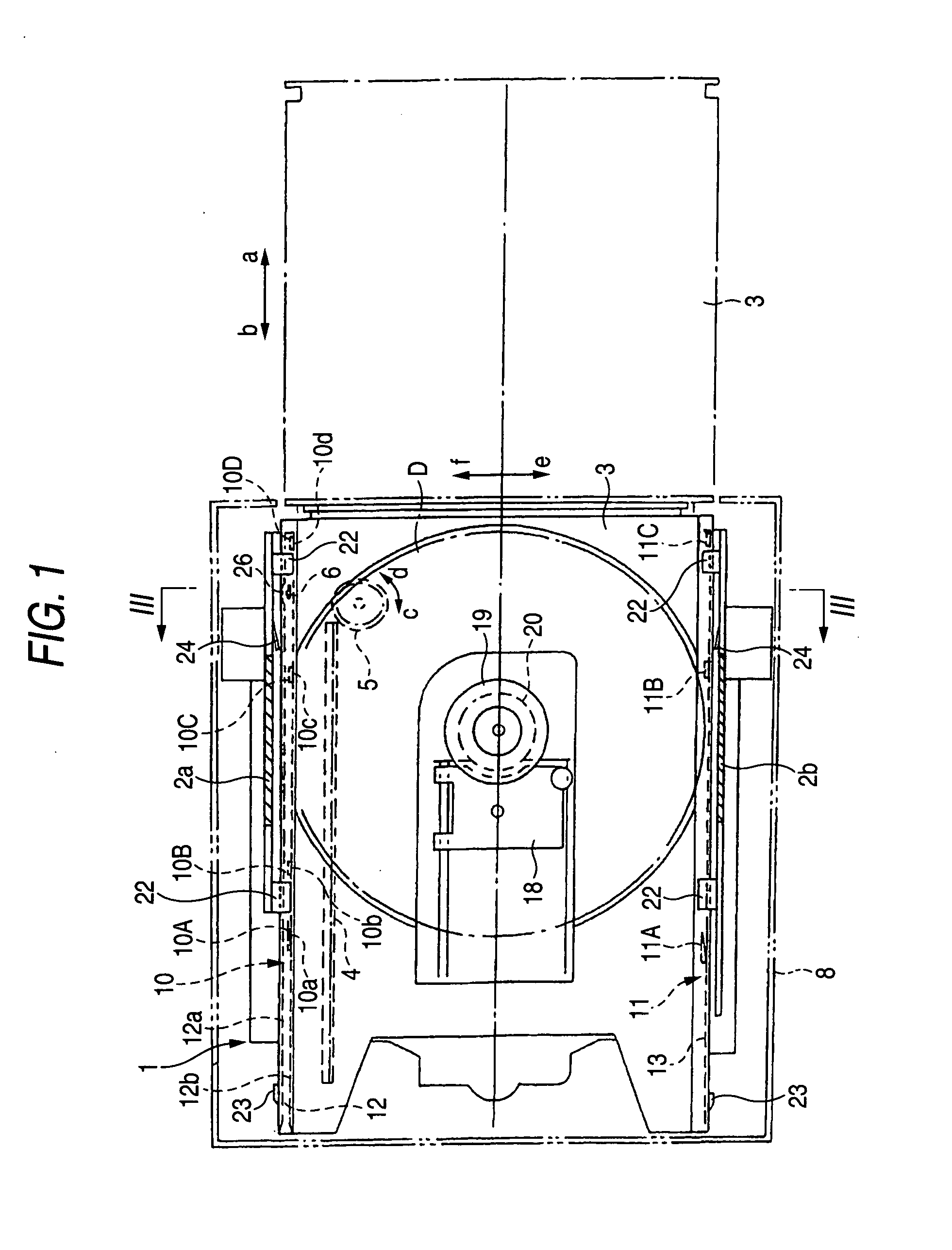
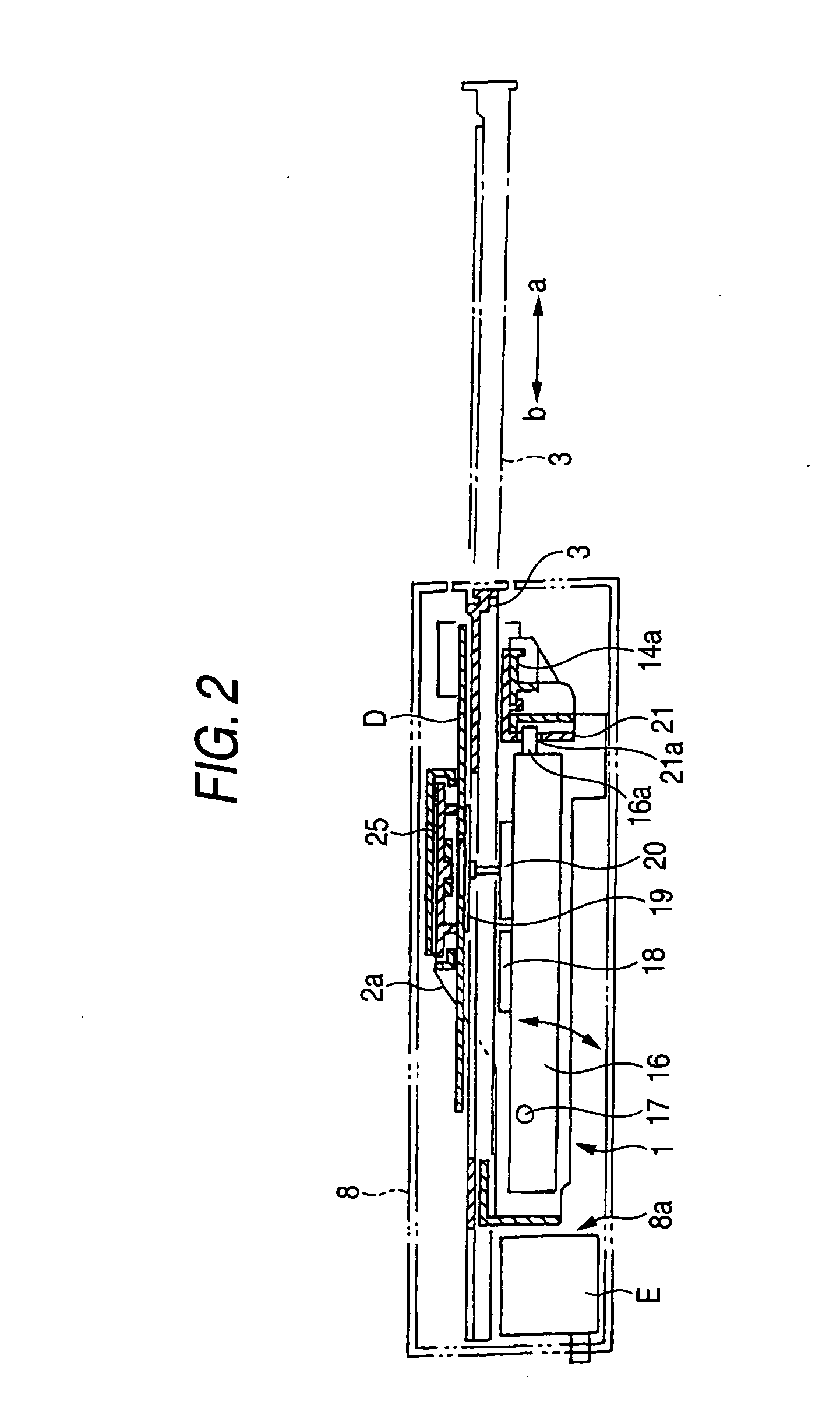
[0042]FIG. 1 through FIG. 5 show a disk player according to an embodiment of the invention, receiving bases 9 are provided at both side plate portions 2a, 2b of a cabinet 1 made of a synthetic resin arranged in a casing 8, the receiving bases 9 are provided with a pair of left and right guide member 10, 11 comprising pluralities of guide pieces 10A through 10D, 11A through 11C aligned at predetermined intervals in a direction of forward and rearward a, b, guide grooves 12 substantially in a U-like shape and guide grooves 13 formed substantially in a U-like shape and formed at both side edges of a lower face of a tray 3 made of a synthetic resin are respectively fitted to the respective guide members 10, 11, a pair of front and rear lateral beam portions 14a, 14b are hung between the both side plate portions 2a, 2b of the cabinet 1, a rectangular through hole 15 is penetrated to a portion of the front side lateral beam portion 14a opposed to the guide groove 12 substantially in the U...


PUM


Abstract

In guide grooves formed at both side edges of a lower face of a tray and fitted to a pair of left and right guide members of a cabinet, the guide groove substantially in a U-like shape on one side is inserted with a front end portion of an elastic plate integrally projected at a front portion of the cabinet, a recess portion is formed at a portion of one side face of the guide groove 12 opposed to the elastic plate in a state of containing the tray into the cabinet, and formed such that by bringing the one side face of the guide groove 12 into elastic contact with the elastic plate opposed to the recess portion in moving the tray forward, other side face of the guide groove is brought into contact with reference guide faces of the guide member on one side to thereby prevent the tray from being inclined.

Description

BACKGROUND OF THE INVENTION [0001] 1. Filed of the Invention [0002] The present invention relates to a disk player for reproducing, recording or erasing an optical disk or a photomagnetic disk (hereinafter, abbreviated as disk of DVD•RW or the like. [0003] 2. Description of the Related Art [0004] There is a prior art disclosed in JP-A-2003-16712 as a technology of a disk player. According to the disk player, as shown by FIG. 12A, a tray 3 made of a synthetic resin for a disk D is arranged to be movable forward and rearward a, b between both side plate portions 2a, 2b of a cabinet 1 made of a synthetic resin, a rack 4 is formed at a vicinity of one side edge of a lower face of the tray 3 along a direction of forward and rearward a, b, a pinion 5 rotatable regularly and reversely c, d is provided at the cabinet 1 to be opposed to the rack 4, the tray 3 is moved forward a by rotating the pinion 5 regularly c based on an unloading signal, at this occasion, as shown by imaginary lines, t...

Claims


Application Information

Patent Timeline
IPC IPC(8): G11B17/04G11B33/02G11B17/056
CPCG11B33/02G11B17/056
Inventor SAKAGAMI, KATSUYA
Owner FUNAI ELECTRIC CO LTD
Why Eureka
Try Eureka