Hydrodynamic braking system provide with a retarder

a technology of hydraulic braking system and retarder, which is applied in the direction of braking system, mechanical apparatus, braking element arrangement, etc., can solve the problems of additional mechanical losses, complicated construction, and increased operating costs, and achieve low flow resistance and cooling in non-braking operation.

Inactive Publication Date: 2005-01-27
VOITH TURBO GMBH & CO KG
View PDF4 Cites 12 Cited by
  • Summary
  • Abstract
  • Description
  • Claims
  • Application Information

AI Technical Summary

Benefits of technology

The patent text describes a way to reduce the resistance of a throttle element in a discharge line. This is achieved by installing a continuously opened flow cross section in the throttle element. This design allows for better cooling and emptying of the retarder, even when there is no external energy supply. Overall, this results in improved performance and efficiency of the system.

Problems solved by technology

The patent text describes a problem with a current hydrodynamic braking system that uses a retarder. The current system requires additional energy to return excess operating medium from the retarder and has complicated construction and operation. The technical problem is to create a hydrodynamic braking system with a retarder that allows for more efficient evacuation of the retarder to a predetermined level, without requiring additional energy or complicated construction and operation.

Method used


Image

  • Hydrodynamic braking system provide with a retarder
  • Hydrodynamic braking system provide with a retarder
  • Hydrodynamic braking system provide with a retarder

Examples


Embodiment Construction

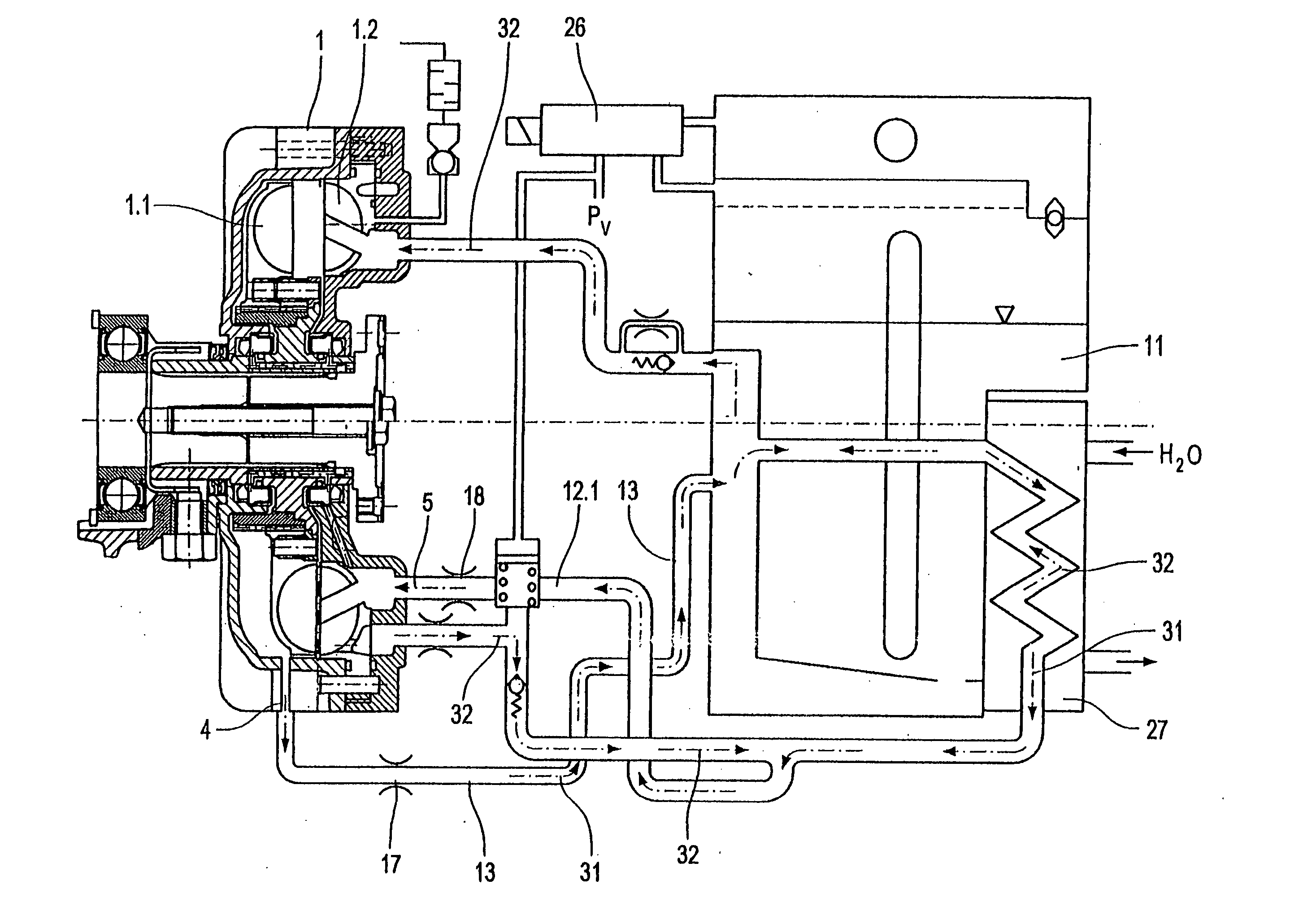
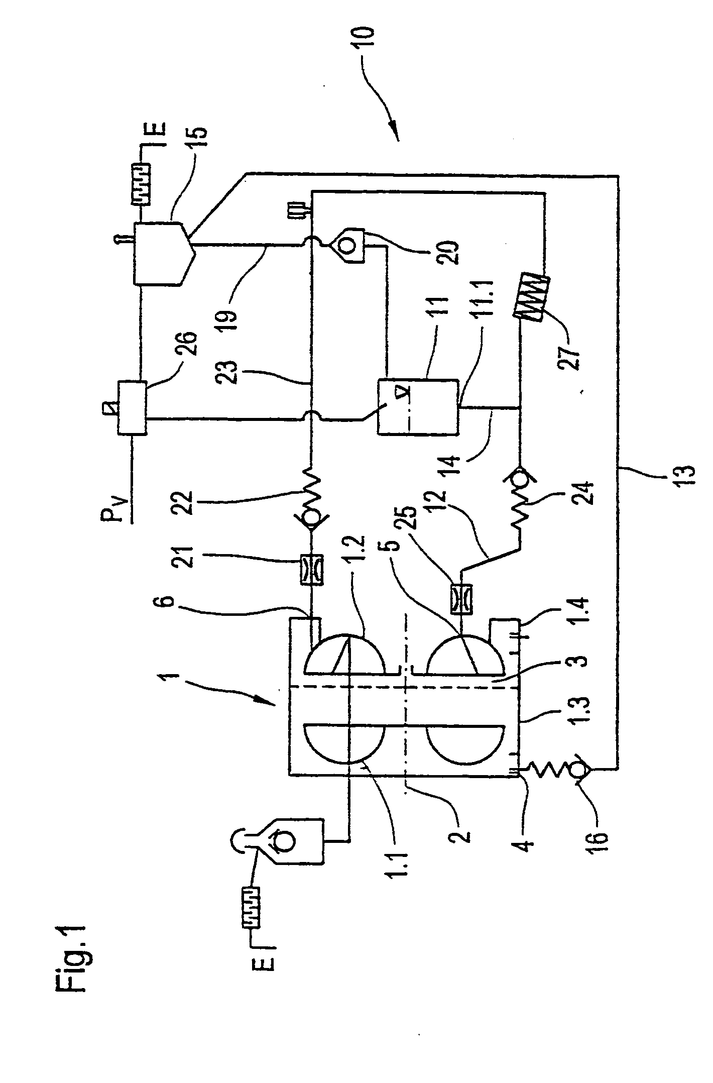
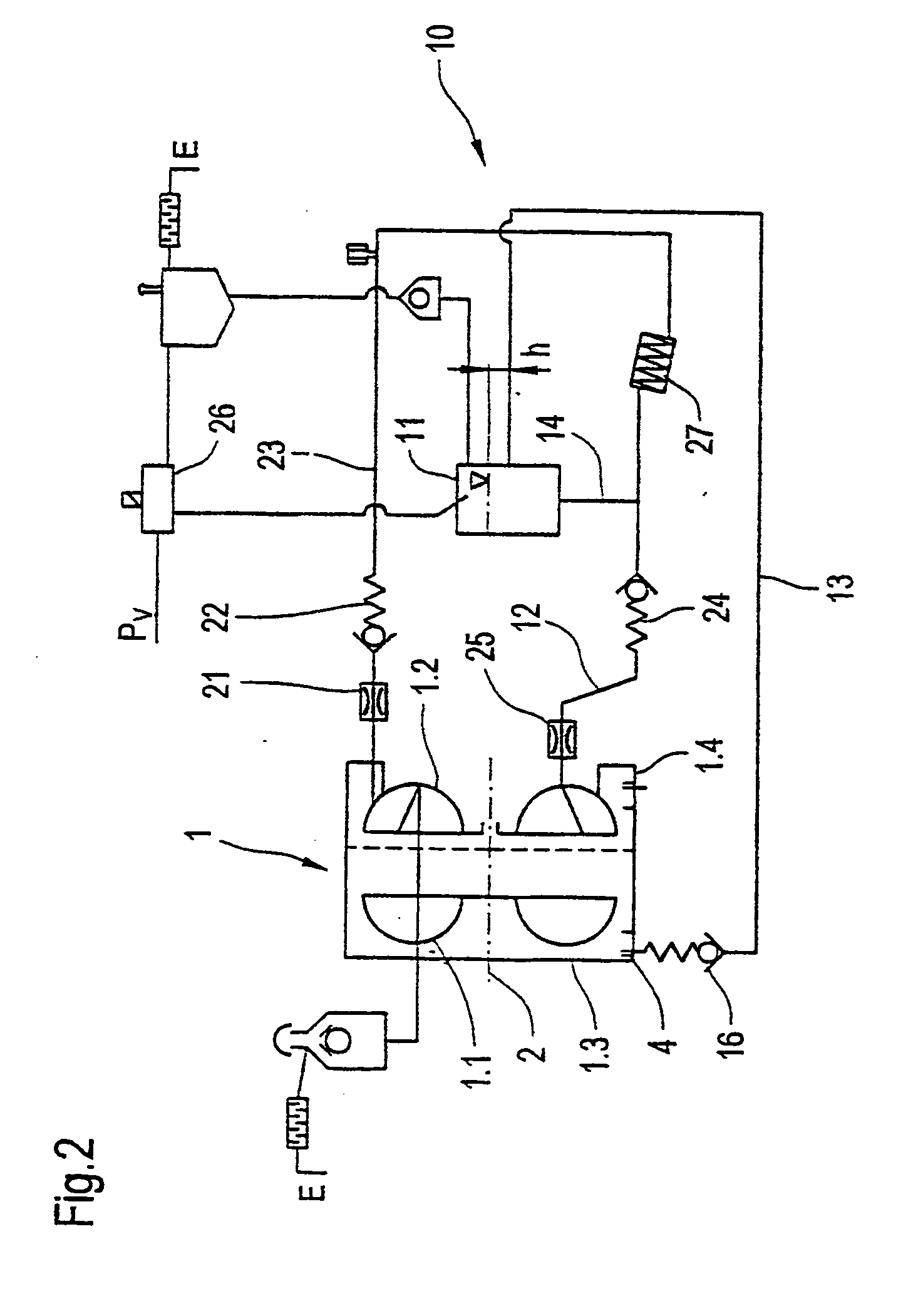
[0028] Referring now to the drawings, and more particularly to FIG. 1 there is shown a schematic illustration of retarder 1, including rotor 1.1 and stator 1.2. FIG. 1 further illustrates rotor housing 1.3 and stator housing 1.4. The non-braking operational condition is illustrated, that is, rotor 1.1 has been moved from stator 1.2 in axial direction, the direction of the axis of rotation 2 of the rotor, into a position of a greater distance, in order to avoid ventilation losses.

[0029] Outlet 4 is located in rotor housing 1.3 at a defined distance from the axis of rotation of the rotor. In this example the direction of the outlet is aligned radially, that is vertical to the rotor's axis of rotation. As indicated, projections, or a pipe section protrude radially in direction of rotor 1.1 beyond the inner surface of rotor housing 1.3. The height of this protrusion determines the residual operating medium that remains in the retarder housing. It is also possible to arrange the outlet ...


PUM


Abstract

A hydrodynamic braking system with a retarder including a rotor arranged in a rotor housing and a stator arranged in a stator housing, whereby the rotor and the stator together form a working space. The rotor is axially movable relative to the stator, from a first position (braking operating position) to a second position (non-braking operating position), and vice versa. The axial distance between the rotor and the stator in the non-braking operating position is a multiple of the distance separating them in the braking operating position. According to one aspect of the present invention the rotor housing includes an outlet that is located at a distance from the axis of rotation of the rotor and is open toward the rotor in the non-braking operating position such that the operating medium collected by the rotor is conveyed outside the working space through the outlet.

Description


Claims


Application Information

Patent Timeline
Owner VOITH TURBO GMBH & CO KG
Why Eureka
Try Eureka