Electrolysis vessel and apparatus for generating electrolyzed water

An electrolytic cell and water electrolysis technology, applied in the electrolysis process, electrolysis components, electrochemical water/sewage treatment, etc., can solve problems such as corrosion of metal parts of pipelines, and achieve the effect of reducing flow resistance, small resistance and small load

Inactive Publication Date: 2006-12-13
HONDA MOTOR CO LTD
View PDF1 Cites 21 Cited by
  • Summary
  • Abstract
  • Description
  • Claims
  • Application Information

AI Technical Summary

Problems solved by technology

Therefore, if the acidic electrolyzed water with a large amount of chlorine ions remaining is used for a long period of time, it may corrode the pipes of the electrolyzed water generating device, the metal parts of the distribution target (spray target), etc.

Method used


Image

  • Electrolysis vessel and apparatus for generating electrolyzed water
  • Electrolysis vessel and apparatus for generating electrolyzed water
  • Electrolysis vessel and apparatus for generating electrolyzed water

Examples


Embodiment 1

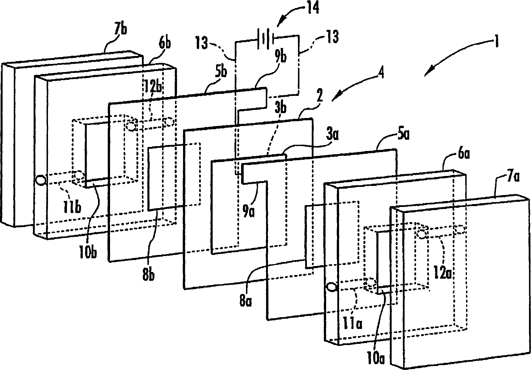
[0058] In this example, in figure 1 In the shown electrolytic cell 1, the area of ​​the electrodes 3a, 3b facing the electrolytic chambers 10a, 10b is set as 16cm 2 , at a flow rate of 16 mL / min, distilled water is supplied to the electrolysis chamber 10a on the anode side, salt water (sodium chloride aqueous solution) with a concentration of 0.8 g / L is supplied to the electrolysis chamber 10 b on the cathode side, and 0.5 g / L is supplied to the electrodes 3 a and 3 b. A constant current for electrolysis.

[0059] At this time, the voltage was about 7V, the pH of the acidic electrolyzed water obtained in the electrolysis chamber 10a was 1.94, and the available chlorine concentration was 50 ppm. The results are shown in Table 1.

[0060] Add dropwise 0.1mol / L silver nitrate solution of 0.5mL in the described acidic electrolytic solution of 5mL, generate the white precipitation of silver chloride, measure the amount of transmitted light of the solution that has produced white ...

Embodiment 2

[0073] In this embodiment, firstly, the electrode substrate, the catalytic base and the binder are mixed in a weight ratio of 100:5:7 to prepare a paste mixture. The electrode substrate uses titanium carbide (TiC) with a mesh size of 325 or less, and the catalyst uses a mixture of platinum black and iridium black at a weight ratio of 3:7. And, as a binder, a solution obtained by dissolving polyvinyl alcohol having a saponification rate of 100% in a water / ethanol mixed solvent (volume ratio of 1:1) at a concentration of 2% by weight was used. The viscosity is 15cps~25cps.

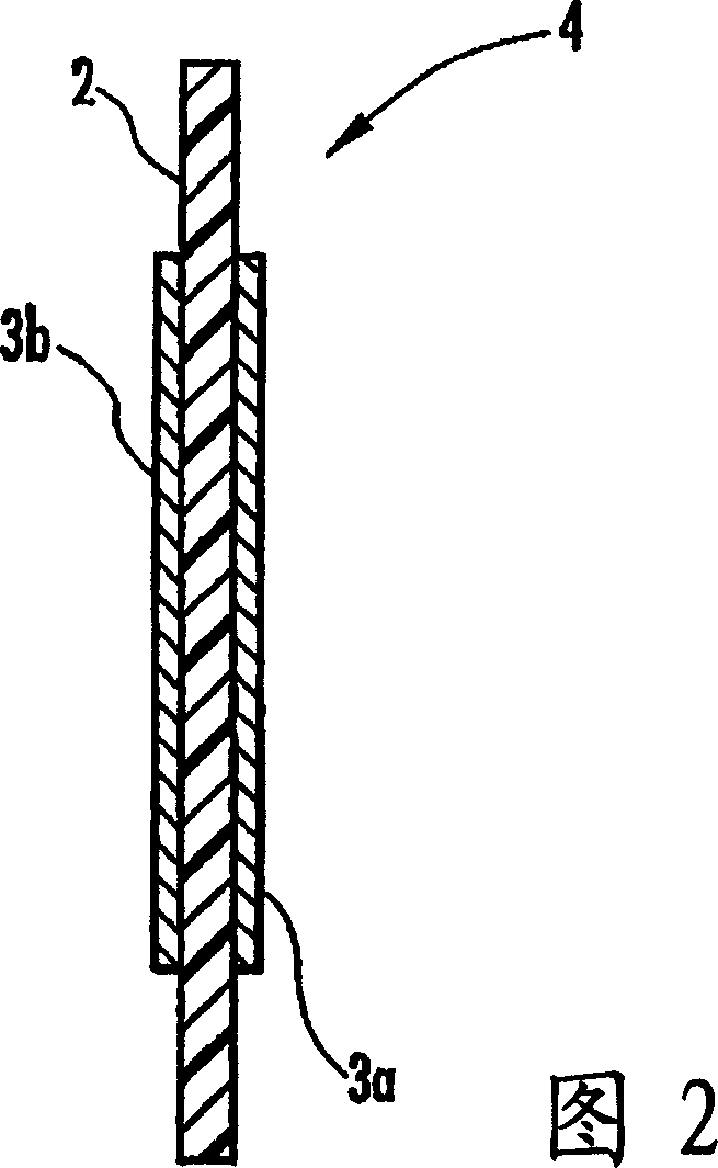
[0074] Next, the paste mixture was applied to an anion exchange membrane (SELEMION membrane (registered trademark) AMV manufactured by Asahi Glass Co., Ltd.) having a thickness of about 100 μm as the ion permeable membrane 2, dried, and then heated at 80° C. The membrane-electrode structure 4 was formed by heating and pressurizing for 30 minutes under the condition of 10 MPa. The surface resistance of the ...


PUM

PropertyMeasurementUnit
thicknessaaaaaaaaaa

Abstract

Disclosed are an electrolysis vessel and an apparatus for generating electrolyzed water which are small in size, excellent in electrolysis efficiency, and enable to reduce the anion concentration in the acidic electrolyzed water. The electrolysis vessel comprises electrolysis chambers (10a, 10b) arranged opposite to each other with an ion-permeable separating membrane (2) interposed between, raw material water supply means (11a, 11b), electrodes (3a, 3b) so arranged as to have the separating membrane (2) between them, and electrolyzed water taking-out means (12a, 12b). The separating membrane (2) is an anion permeable membrane, and the electrodes (3a, 3b) are formed on respective sides of the anion permeable membrane (2) in an appressed manner, while leaving a portion of the anion permeable membrane (2) exposed. Only raw material water supplied to the cathode side electrolysis chamber (10b) contains an electrolyte. The electrodes (3a, 3b) are porous bodies and contain an electrode base composed of a powder titanium compound such as TiC or TiN, a catalyst such as platinum black or iridium black, and a binder such as PVA. The electrodes (3a, 3b) may have a mesh-like shape or a comb-like shape, and are formed by applying a conductive paste containing a conductive powder on respective sides of the anion permeable membrane (2) and heating or pressurizing the thus-applied paste.

Description

technical field [0001] The present invention relates to an electrolytic cell and an electrolyzed water generating device using the electrolytic cell to generate electrolyzed water. In the electrolytic cell, a pair of electrolytic chambers are arranged facing each other with an ion-permeable diaphragm interposed therebetween. A pair of electrodes provided in each electrolytic chamber The raw water supplied to the pair of electrolysis chambers is electrolyzed by applying a voltage to the pair of electrodes across the diaphragm. Background technique [0002] There is known an electrolyzed water generating device that generates electrolyzed water using an electrolyzed cell having a pair of electrolyzed chambers disposed opposite to each other with an ion-permeable diaphragm interposed therebetween, and an electrolyzed chamber disposed in each electrolyzed chamber with the diaphragm interposed therebetween. a pair of electrodes. By using the electrolyzed water generating device,...

Claims


Application Information

Patent Timeline
Patent Type & Authority Applications(China)
IPC IPC(8): C02F1/46C25B11/04C25B9/10C25B9/19C25B9/23
CPCY02E60/366
Inventor 宫下公一
Owner HONDA MOTOR CO LTD
Why Eureka
Try Eureka