Two-stroke internal combustion engine

a two-stroke, internal combustion engine technology, applied in combustion engines, machines/engines, cylinders, etc., can solve the problems of limited amount of fresh air that can be added, difficult control of air-to-fuel ratio in such engines, operational difficulties, etc., to reduce the effect of package size and weight, and reduce the overall length of the piston

Inactive Publication Date: 2006-08-01
HUSQVARNA AB
View PDF62 Cites 21 Cited by
  • Summary
  • Abstract
  • Description
  • Claims
  • Application Information

AI Technical Summary

Benefits of technology

[0032]In another aspect, a new arrangement for a crankarm pin is disclosed with particular reference being made to FIGS. 6 and 7. From these depictions, it may be appreciated that a lengthwise abbreviated crankarm pin is mounted between a pair of recesses in the piston body. Because the ends of the crankarm pin are anchored further inward from what would otherwise be the internal piston wall, the length of the pin required to make the extension across the interior space of the piston is less. In another beneficial aspect, the illustrated placement of the end portions of the crankarm pin exclusively within the confines of the pair of recesses assures that no extra length is required in the piston's body height for the pin's accommodation. This reduces the overall length of the piston, and therefore enables a corresponding reduction in package size and weight of the two-stroke internal combustion engine that incorporates this crankarm pin configuration. This is a significant advantage in view of the fact that package size and weight are always of utmost concern, especially in such applications as hand tools where user fatigue will be commensurately reduced by any reductions in these characteristics of the powering two-stroke internal combustion engine.
[0033]In still another aspect, the present invention teaches a configuration in which because at least one connecting port in the engine's cylinder wall is arranged so that it is in connection with piston positions at the top dead center and is connected with flow paths embodied in the piston, the supply of fresh air to the upper part of the transfer ducts can be arranged entirely without check valves. This can take place because for piston positions at or near the top dead center, there is an underpressure in the transfer duct in relation to the ambient air. Thus, a piston ported air passage without check valves can be arranged, which is a big advantage. Because the air supply has a very long period, a substantial amount of air can be delivered so that a high exhaust emissions reduction effect can be achieved. Control is applied by means of a restriction valve in the air inlet, controlled by at least one engine parameter. Such control is of a significantly less complicated design than a variable inlet. The air inlet has preferably two connecting ports, which in one embodiment of the invention, are located so that the piston is covering them at its bottom dead center. The restriction valve can suitably be controlled by the engine speed, alone or in combination with another engine parameter.
[0034]In yet another aspect, the invention takes the form of a combustion engine configured so that the air passage is arranged from an air inlet equipped with a restriction valve, controlled by at least one engine parameter such as the carburetor throttle control. The air inlet is provided via at least one connecting duct channeled to at least one connecting port in the cylinder wall of the engine that is arranged so that it, in connection with piston positions at the top dead center, is connected with flow paths embodied in the piston. These flow paths extend to the upper part of a number of transfer ducts, and each flow path in the cylinder and piston is to a great extent arranged in the cylinder's lateral direction. In one aspect, the connecting port and adjacent scavenging port of the cylinder are shifted sideways in relation to each other along the periphery of the cylinder wall. In other aspect, the transfer ducts of the cylinder are essentially running in the cylinder's lateral direction away from each scavenging port respectively. This configuration may be characterized as being of a tangential nature relative to the circumference of the cylinder wall. By this arrangement a flow of air through the cylinder with very few and moderate curves is achieved, thereby achieving low flow resistance.

Problems solved by technology

They beneficially reduce fuel consumption and exhaust emissions; but negatively, the air-to-fuel ratio in such an engine is difficult to control.
The amount of fresh air that can be added is therefore limited because of the short time period that air is supplied and because the presence of the necessary check valve(s) causes substantial resistance to flow when it does occur.
Such valves frequently have a tendency to come into resonant oscillations causing operational difficulties at high rotational engine speeds which two-stroke internal combustion engines often reach.
Still further, the added component of the reed valve adds to the total cost of the engine, as well as increases the number of constituent engine components further complicating the design.
This is, however, is an unnecessarily complicated solution.
In all embodiments, however, these piston recesses have, where they meet a respective transfer duct, a very limited height that is essentially equal to the height of the actual transfer port.
This can complicate the control of the total air-to-fuel ratio of the engine.
This also means that the amount of air that can be delivered to the transfer duct is significantly limited because the underpressure condition utilized to drive this additional air has decreased significantly since the inlet port has already been open during a certain period of time when the air supply is opened.
A consequence of such a design is that it inhibits the possibilities for reducing the engine's fuel consumption and exhaust emissions.

Method used


Image

  • Two-stroke internal combustion engine
  • Two-stroke internal combustion engine
  • Two-stroke internal combustion engine

Examples


Embodiment Construction

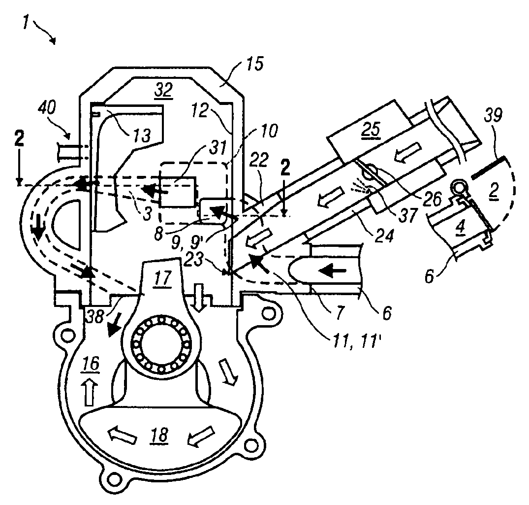
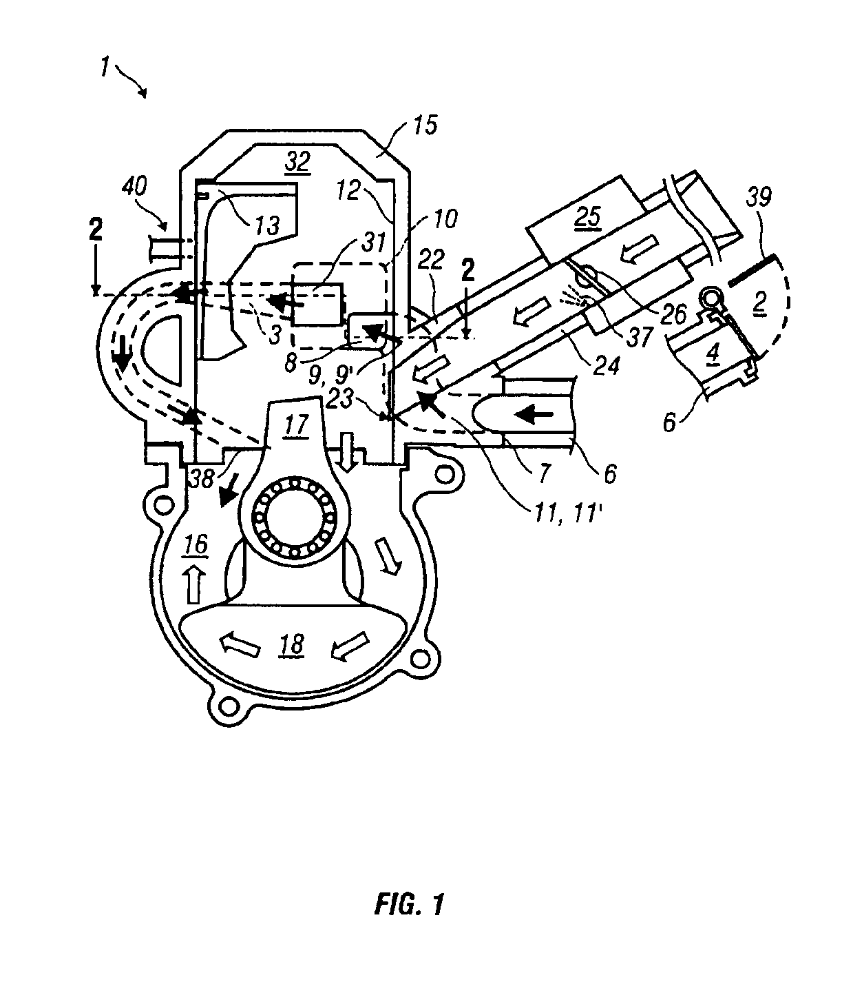
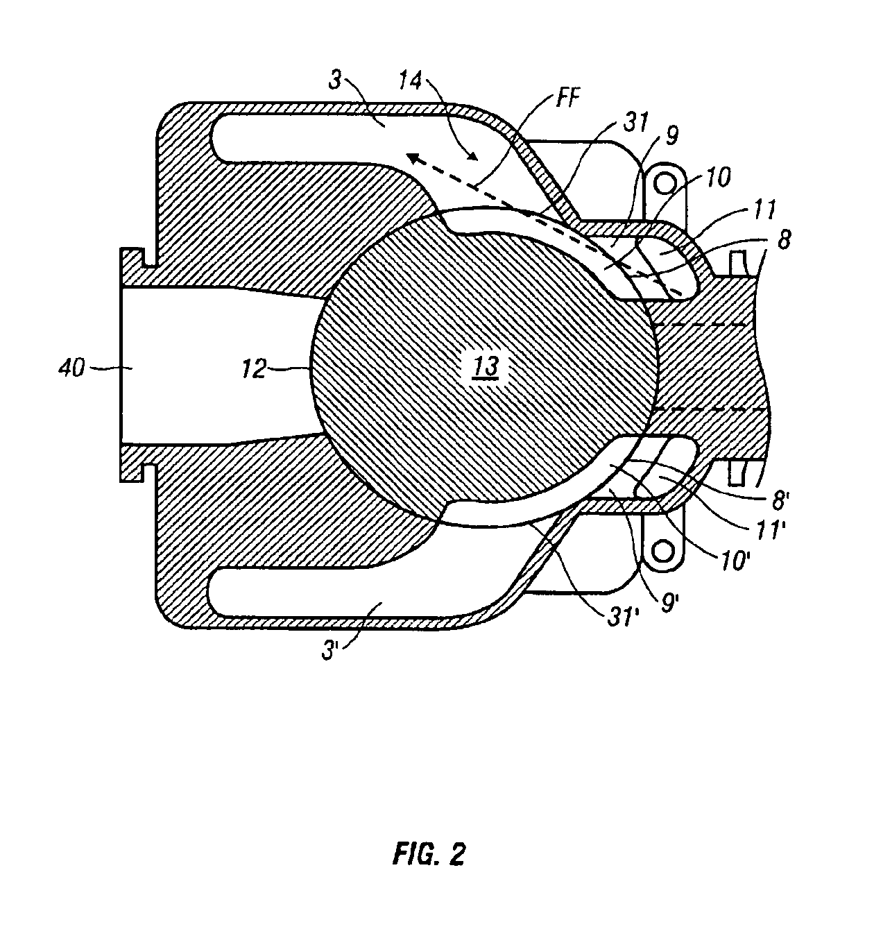
[0043]The inventions will be described in greater detail and by way of various embodiments thereof with reference to the accompanying drawing figures. For parts that are symmetrically located on the engine, the part on the one side has been given a numeric designation while the part on the opposite side has been given the same numeric designation, but with a prime (′) symbol appended thereto. In general, when referring to the drawings, the corresponding parts designated with a prime symbol are located above the plane of the paper and are therefore not expressly shown in some views.

[0044]In FIG. 1, an internal combustion engine 1 is shown configured according to the teachings of the presently disclosed invention(s). It is of the two-stroke type and has transfer or scavenging ducts 3, 3′. The transfer duct 3′ is not visible in this figure because it would be located above the plane of the paper. The engine 1 has a cylinder 15 and a crankcase 16, a piston 13 with a connecting rod 17 an...


PUM


Abstract

Crankcase scavenged two-stroke internal combustion engine (1), in which a piston ported air passage is arranged between an air inlet (2) and the upper part of a number of transfer ducts (3, 3′). The air passage is arranged from an air inlet (2) equipped with a restriction valve (4), controlled by at least one engine parameter, for instance the carburetor throttle control. The air inlet extends via at least one connecting duct (6, 6′) to at least one connecting port (8, 8′) in the engine's cylinder wall (12). The connecting port (8, 8′) is arranged so that it in connection with piston positions at the top dead center is connected with flow paths (10, 10′) embodied in the piston (13), which extend to the upper part of a number of transfer ducts (3, 3′). Each flow path through the cylinder and piston is to a great extent arranged in the cylinder's lateral direction, on the one hand in that the connecting port (8, 8′) and adjacent scavenging port (31, 31′) of the cylinder are shifted sideways in relation to each other along the periphery of the cylinder wall (12), and on the other hand in that the transfer ducts (3, 3′) of the cylinder are running essentially in the cylinder's lateral direction away from each transfer port (31, 31′) respectively, i.e. tangentially in relation to the circumference of the cylinder wall (12).

Description

CROSS REFERENCE TO RELATED APPLICATIONS[0001]The present application is a (1) continuation-in-part of PCT / SE00 / 00058 filed 14 Jan. 2000 which designates the United States; (2) a continuation-in-part of U.S. application Ser. No. 09 / 483,478 filed May 30, 2000 now abandoned and priority is claimed through that application to SE-9900138-0 filed 19 Jan. 1999; and (3) a continuation-in-part of PCT / SE00 / 00059 filed 14 Jan. 2000 which designates the United States. The disclosures of each of these applications are expressly incorporated herein by reference in their entireties.BACKGROUND OF INVENTION[0002]1. Technical Field[0003]The subject invention refers to a two-stroke crankcase scavenged internal combustion engine in which one or more piston ported air passages are arranged between one or more air inlets and the upper part or ends of one or more corresponding transfer or scavenging ducts. Fresh air is added at the top of the transfer ducts and is intended to serve as a buffer against the...

Claims


Application Information

Patent Timeline
Patent Type & Authority Patents(United States)
IPC IPC(8): F02B25/20F02B25/14F02B25/22F02B33/04F02B63/02F02B75/02F02F1/22F02F3/24
CPCF02B25/14F02B25/22F02B33/04F02F3/24F02F1/22F02B63/02F02B2075/025
Inventor CARLSSON, BOEKDAHL, ROYSTROM, HANS
Owner HUSQVARNA AB
Why Eureka
Try Eureka