Compact clamping cartridge for panel-type products

a clamping cartridge and compact technology, applied in the field of clamping equipment, can solve the problems of cumbersome solutions, inefficient and/or inability to meet user-defined requirements, and inability to randomly access, so as to reduce the height of the clamping cartridge, simplify the operation of the clamping, and reduce the number of components.

Inactive Publication Date: 2005-01-27
1546300 ONTARIO
View PDF9 Cites 23 Cited by
  • Summary
  • Abstract
  • Description
  • Claims
  • Application Information

AI Technical Summary

Benefits of technology

[0030] The alternate clamping cartridge still uses a series of rotatable tapered cylindrical cam wheels disposed on a rotatable cam shaft to ultimately effect opening and closing of the clamps. However, by disposing the cam wheels generally within the clamps and by providing apertures or slots in the jaws of the clamps to accommodate the cam shaft, a considerable reduction in the height of the cartridge can be realized. The cam shaft is rotatably supported in bearings and a detachable handle is provided with which the shaft can be rotated.
[0031] Besides being more compact, this embodiment significantly reduces the number of components and simplifies the operation of the clamps. Furthermore, it reduces the amount of rotational input required to effect opening and closing of the clamps. The cartridge is operational to cause the clamps to open in unison and to permit the jaws of the clamps to close or clamp independently against one or more objects which may have been placed therebetween.
[0032] The main features and advantages of the clamping cartridges according to the invention are: versatility in typo-dimensional product sequencing and access patterns, simplicity of operation and ease of maintenance.

Problems solved by technology

However, when the items are not identical, any sequenced access must be predetermined which usually entails predetermined loading strategies and, furthermore, random access may simply not be possible.
Moreover, where the items vary in thickness, group clamping typically requires individual (i.e. time-consuming) adjustment of respective clamping mechanisms.
Existing solutions are either cumbersome, inefficient and / or unable to address all of the user-defined requirements.

Method used


Image

  • Compact clamping cartridge for panel-type products
  • Compact clamping cartridge for panel-type products
  • Compact clamping cartridge for panel-type products

Examples


Embodiment Construction

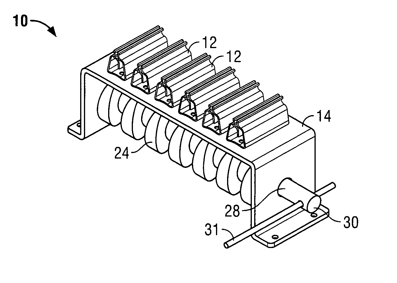
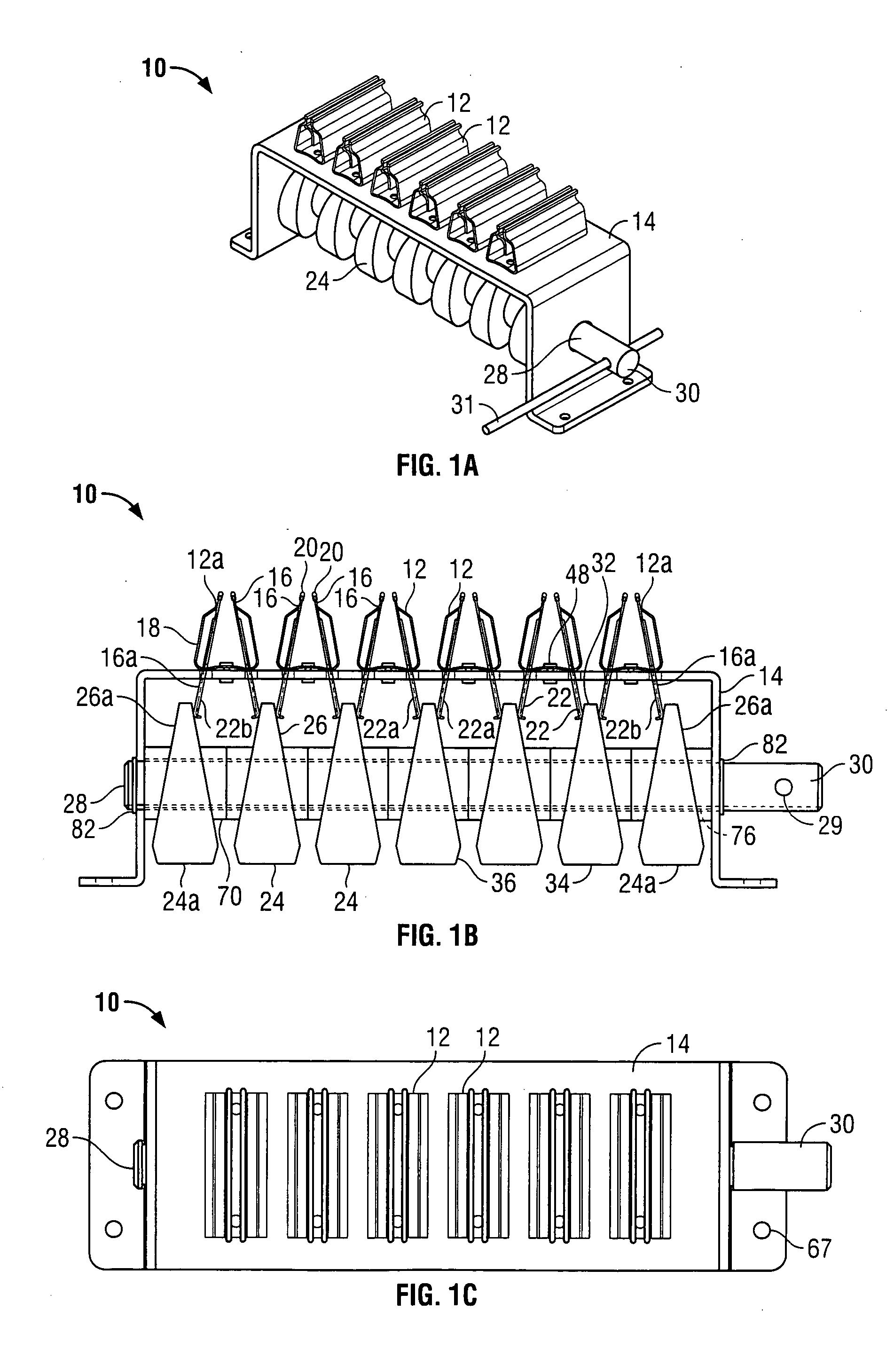
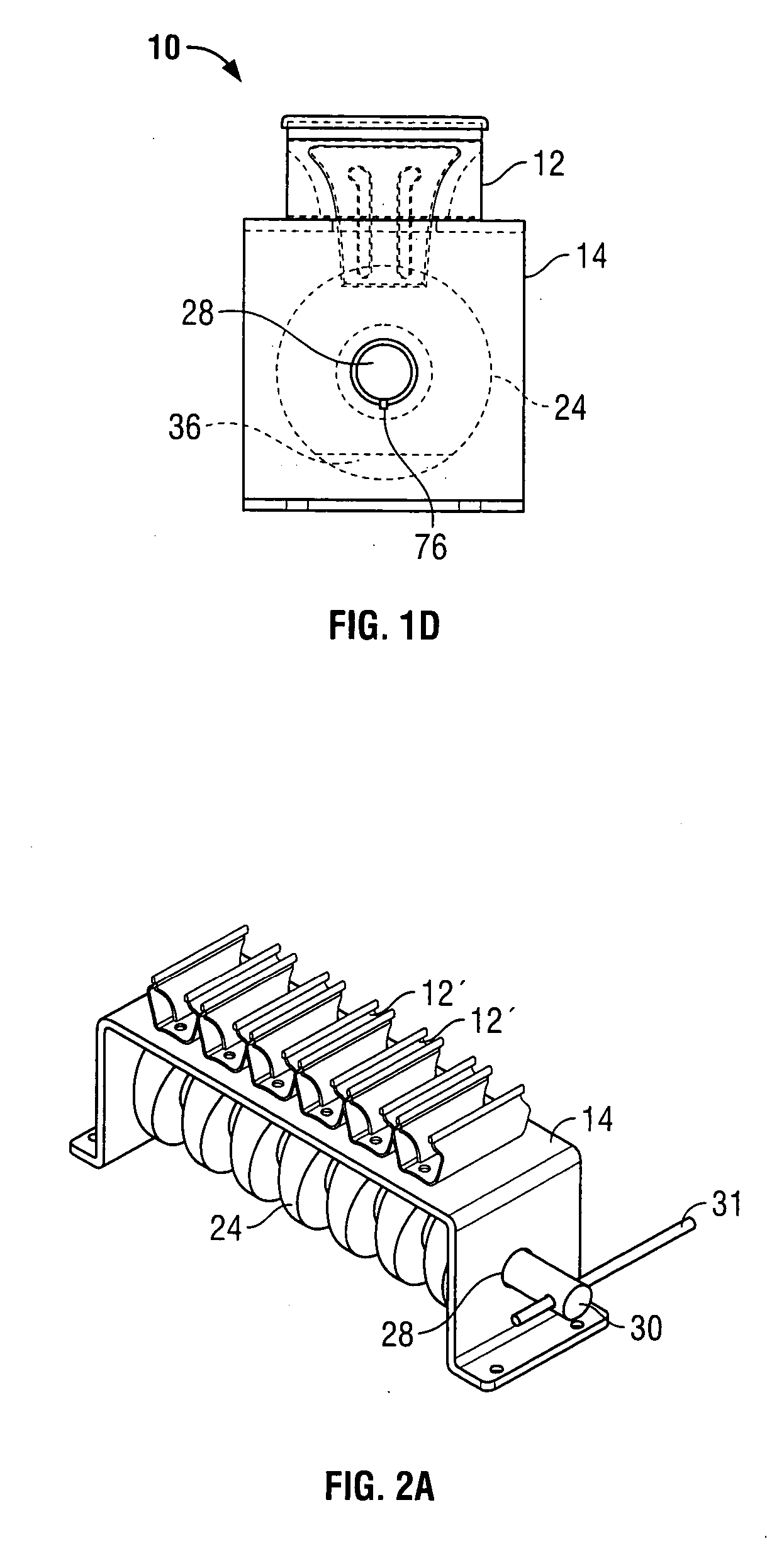
[0066] Referring to FIGS. 1A-1D, there is shown an exemplary arrangement of the clamping cartridge 10 according to the invention. The clamping cartridge 10 comprises a plurality of spaced apart clamping mechanisms 12 arranged on a chassis or frame 14. The clamping mechanisms 12 (hereinafter referred to as clamps 12) have a pair of clamping arms 16 which cooperate with a spring clip 18 which urges the upper ends 20 of arms 16 toward one another in a jaw-like fashion. The lower ends 22 of the clamping arms 16 project through the frame 14 and act as levers which when moved relatively toward one another overcomes the spring force of the spring clip 18 thereby causing the clamp 12 to open (as seen in FIG. 2B). The resiliency of the spring clip 18 biases the clamp 12 toward a closed position.

[0067] The clamping cartridge 10 also includes means to actuate (open / close) the clamps 12 which preferably comprises a series of rotatable cam wheels 24, each of which having a cam surface 26 in con...


PUM


Abstract

A clamping cartridge is provided which comprises a plurality of clamping mechanisms spaced apart on a frame or chassis. The clamping mechanisms are generally oriented perpendicular to their direction of spacing. The clamping mechanisms are of the type which comprise a pair of relatively movable jaws which are normally biased towards one another such that they resist opening and which return to a closed or substantially closed condition in the absence of external forces. An actuator operable in association with the clamping mechanisms serves to open and close the jaws of the clamping mechanisms in unison. The actuator includes a series of rotatable tapered cylindrical cam wheels disposed on a rotatable cam shaft to ultimately effect opening and closing of the clamps, which cam wheels are disposed generally within the clamps. By providing apertures or slots in the jaws of the clamps to accommodate the cam shaft, a considerable reduction in the height of the cartridge can be realized. The cam shaft is rotatably supported in bearings and a detachable handle is provided with which the shaft can be rotated. While the clamps are closeable in unison, they are individually self-adjusting so the extent of closure for each clamp is dependent on the thickness or presence of an inserted article. The clamping cartridges are useful in a variety of applications requiring clamping of one or more articles in a side-by-side relationship. One such application is a transportation/storage rack which includes a plurality of aligned horizontal and vertical clamping cartridges for clamping the edges of glass panels.

Description

CROSS-REFERENCE TO RELATED APPLICATIONS [0001] This application is a continuation-in-part of U.S. application Ser. No. 10 / 730,251 filed Dec. 9, 2003. U.S. application Ser. No. 10 / 730,251 claims the benefit of U.S. Provisional Application No. 60 / 432,023 filed Dec. 10, 2002 and U.S. Provisional Application No. 60 / 488,771 filed Jul. 22, 2003.FIELD OF THE INVENTION [0002] The invention relates to a clamping apparatus for holding and positioning a plurality of items and, more particularly, a clamping cartridge for releasably clamping a plurality of generally planar objects. BACKGROUND OF THE INVENTION [0003] There are numerous instances where a series of sheet or panel-type products need be transported and / or stored. When all such items are identical, there is usually no need to be concerned over loading and unloading sequences. However, when the items are not identical, any sequenced access must be predetermined which usually entails predetermined loading strategies and, furthermore, ra...

Claims


Application Information

Patent Timeline
Patent Type & Authority Applications(United States)
IPC IPC(8): B65D25/10B65D85/48
CPCB65D85/48B65D25/101
Inventor LACATUS, TIBERIU
Owner 1546300 ONTARIO
Why Eureka
Try Eureka